
Antenna simply manufactured according to frequency characteristic

a technology of frequency characteristic and antenna, applied in the direction of antenna earthing, separate antenna unit combination, radiating element structural form, etc., can solve the problems of high manual work, durability problems, etc., and achieve the effect of reducing assembly errors and reducing manufacturing errors of feeding devices

Inactive Publication Date: 2014-07-01
ELECTRONICS & TELECOMM RES INST
View PDF10 Cites 1 Cited by
  • Summary
  • Abstract
  • Description
  • Claims
  • Application Information

AI Technical Summary

Benefits of technology

This design minimizes manufacturing and assembly errors, ensures consistent electrical characteristics, and allows for easy adaptation to different frequency bands by enabling the formation of multiple beams with reduced reflection loss and improved directivity.

Problems solved by technology

To manufacture a large number of individual devices, such a method requires a lot of manual work, and may have problems of durability according to characteristics of the adhesive.

Method used


Image

  • Antenna simply manufactured according to frequency characteristic
  • Antenna simply manufactured according to frequency characteristic
  • Antenna simply manufactured according to frequency characteristic

Examples


Embodiment Construction

[0031]The detailed description is provided to assist the reader in gaining a comprehensive understanding of the methods, apparatuses and / or systems described herein. Various changes, modifications, and equivalents of the systems, apparatuses, and / or methods described herein will likely suggest themselves to those of ordinary skill in the art. Also, descriptions of well-known functions and constructions are omitted to increase clarity and conciseness.

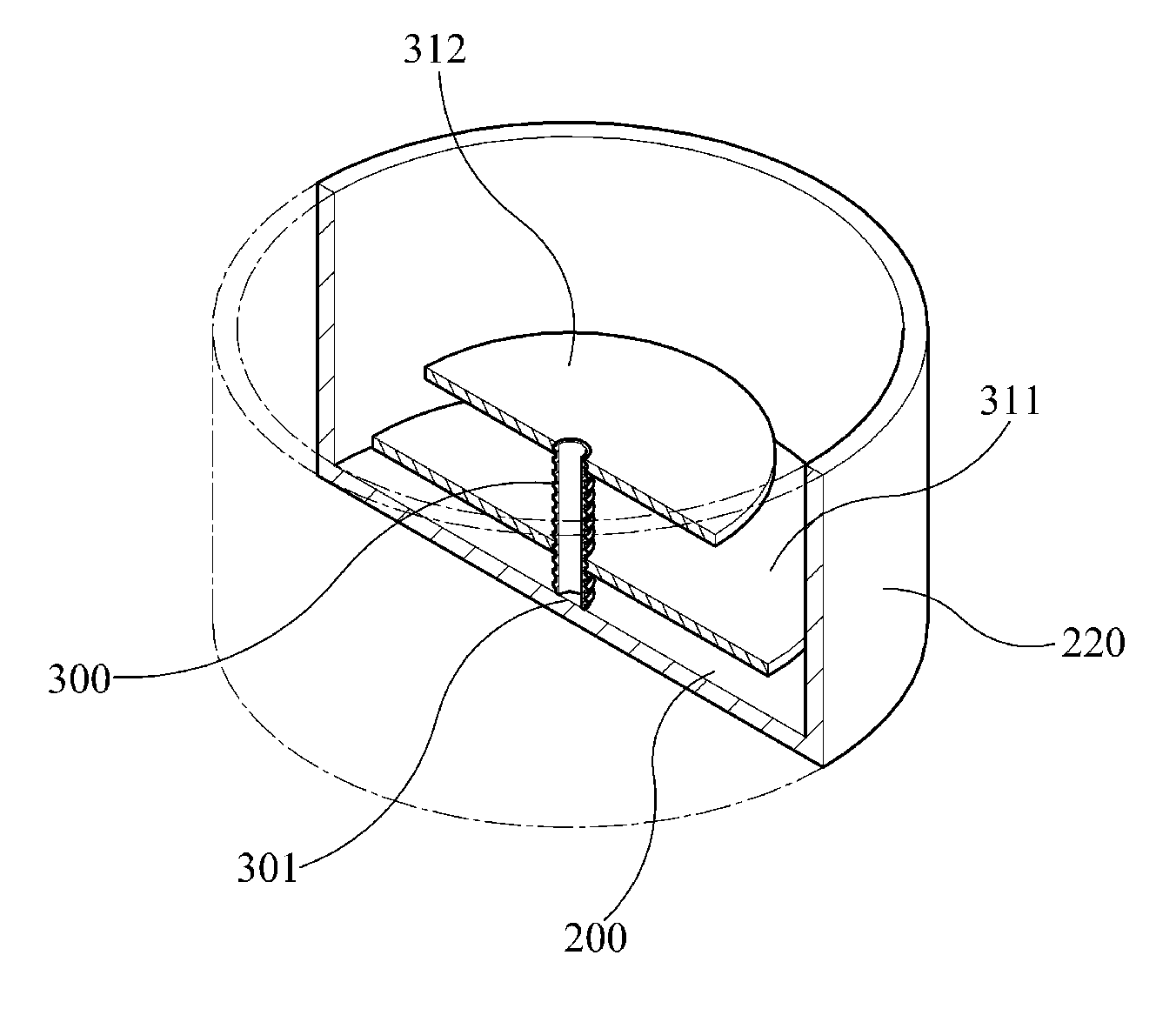
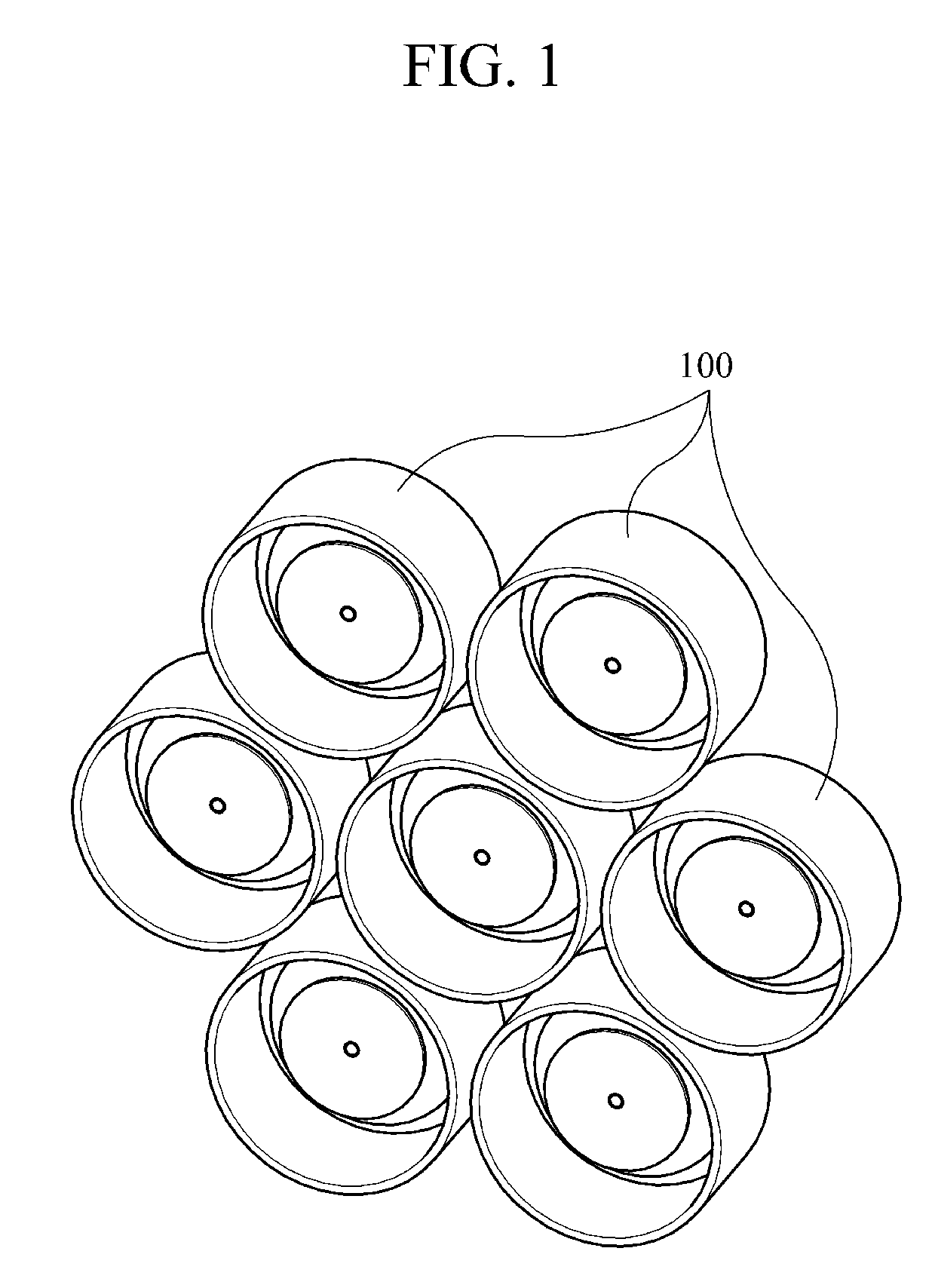
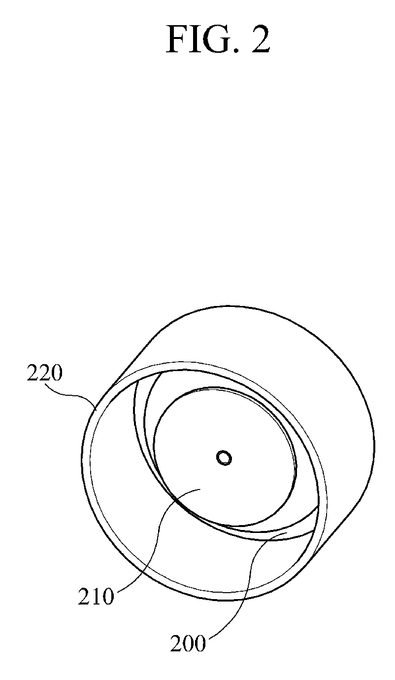
[0032]FIG. 1 shows a disk-shaped antenna 100 forming multiple beams for mobile communication service according to an exemplary embodiment of the present invention.

[0033]The disk-shaped antenna 100 of FIG. 1 forming multiple beams is merely an example consisting of seven individual antenna devices, and the number of devices may vary according to system requirements.

[0034]Needless to say, manufacturing needs to be precisely performed so that feeding devices having the same structure as shown in FIG. 1 can be uniformly used.

[0035]To this en...


PUM


Abstract

Provided is an antenna simply manufactured according to a frequency characteristic. The disk-shaped antenna having a screw tap structure includes a center post having a screw tap, a ground plane, and a disk radiator, so that a distance between a ground plane and a disk radiator can be finely tuned, and manufacturing and assembly error can be reduced to minimize differences in electrical characteristics between devices.

Description

CROSS REFERENCE TO RELATED APPLICATIONS[0001]This application claims priority from Korean Patent Application No. 10-2010-0111012, filed on Nov. 9, 2010, the disclosure of which is incorporated herein in its entirety by reference.BACKGROUND OF THE INVENTION[0002]1. Field of the Invention[0003]The present invention relates to a disk-shaped antenna frequently used in systems requiring many phased-array devices to form multiple beams, and more particularly, to an antenna which allows a resonant frequency of the antenna to be selected according to the size of a disk and feed position and thus, can be simply used according to a frequency characteristic.[0004]2. Description of the Related Art[0005]To provide mobile communication service, the demand for an antenna having a wideband or multi-band frequency characteristic with regards to frequency, and capable of forming multiple beams with regards to service is increasing.[0006]To meet this demand, development of a reflector antenna employin...

Claims


Application Information

Patent Timeline
Patent Type & Authority Patents(United States)
IPC IPC(8): H01Q13/10
CPCH01Q9/0414H01Q1/36H01Q1/48H01Q9/0485H01Q21/061H01Q21/30
Inventor YUN, SO-HYEUN
Owner ELECTRONICS & TELECOMM RES INST
Learn More