Connector for flexible printed circuit board

a flexible printed circuit board and connector technology, applied in the direction of coupling device connection, coupling protective earth/shielding arrangement, two-part coupling device, etc., can solve the problems of reducing the number of parts, impede the stable contact, and increase the risk of noise, so as to reduce the number of parts and reduce manufacturing errors. , the effect of preventing nois

Inactive Publication Date: 2005-04-07
YAMAICHI ELECTRONICS
View PDF56 Cites 23 Cited by
  • Summary
  • Abstract
  • Description
  • Claims
  • Application Information

AI Technical Summary

Benefits of technology

[0016] According to the FPC connector of the present invention, it is possible to reduce the manufacturing error in comparison with the prior art wherein the grounding contact is formed as a separate member and attached to the connector body, whereby the electric contact of the FPC with the grounding contacts is further ensured. As a result, it is possible to prevent noises from exceeding the allowable value. Also, since the grounding contact is formed integral with the metallic shell, it is possible to decrease the number of parts and simplify the production process, whereby the production cost is saved.
[0017] By press-fitting the metallic shell into the contact body from the rear side thereof with the fixing piece, it is possible to easily position the grounding contact.
[0018] Further, by partially cutting the spring piece for the FPC-fixing / removing mechanism from the metallic shell and raising the cut portion, it is possible to reduce the production steps and thereby to save the production cost.
[0019] Also, by providing the FPC-fixing / removing mechanism, the inserted FPC does not fall off from the FPC connector.

Problems solved by technology

This may result in the adverse contact between the grounding contact 104 and the FPC, which impedes the stable contact.
As a result, there is a risk of increasing noises, far from reducing them.

Method used


Image

  • Connector for flexible printed circuit board
  • Connector for flexible printed circuit board
  • Connector for flexible printed circuit board

Examples


Embodiment Construction

[0034] The preferred embodiments of the present invention will be described below with reference to FIGS. 1A to 4B.

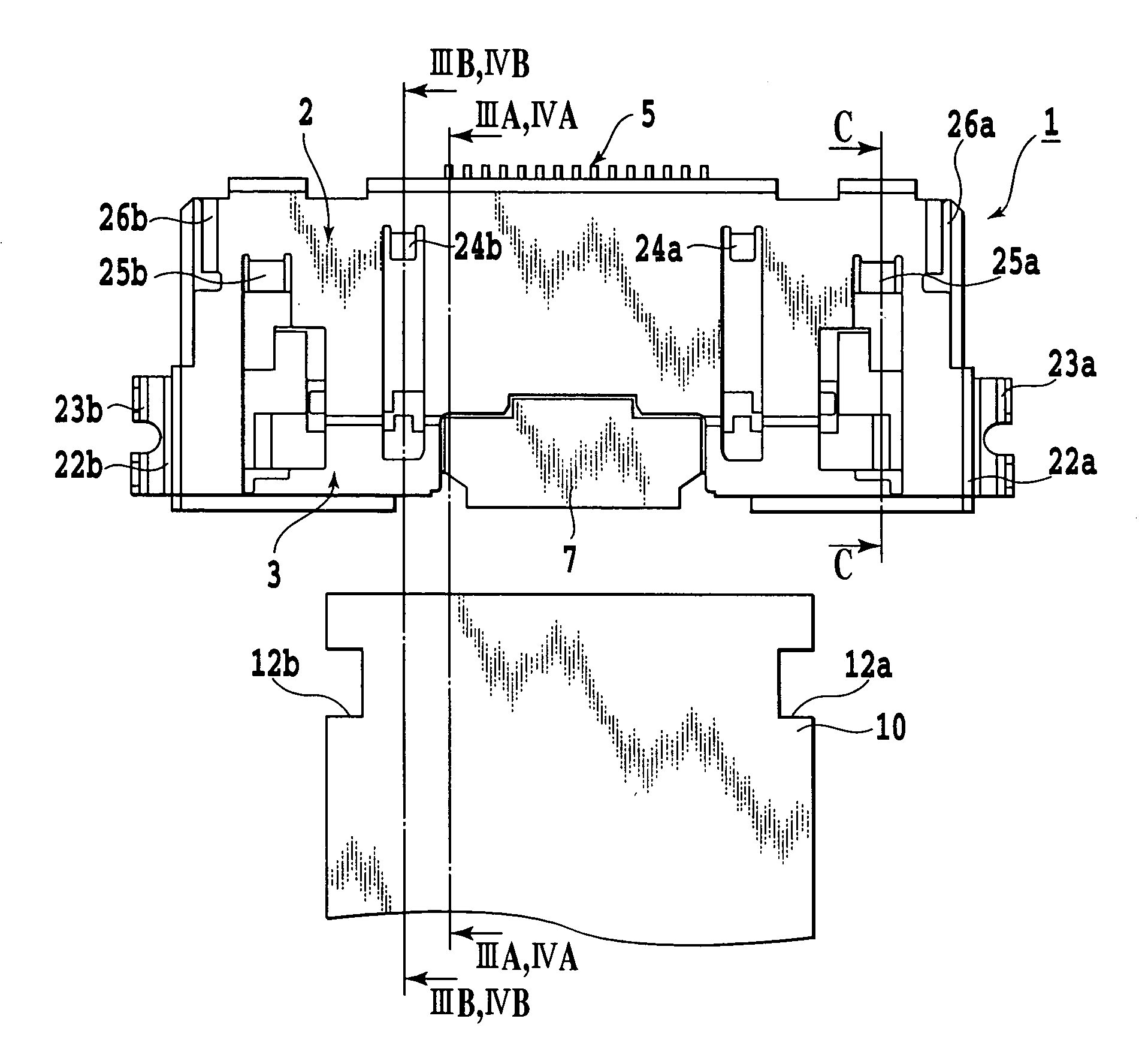
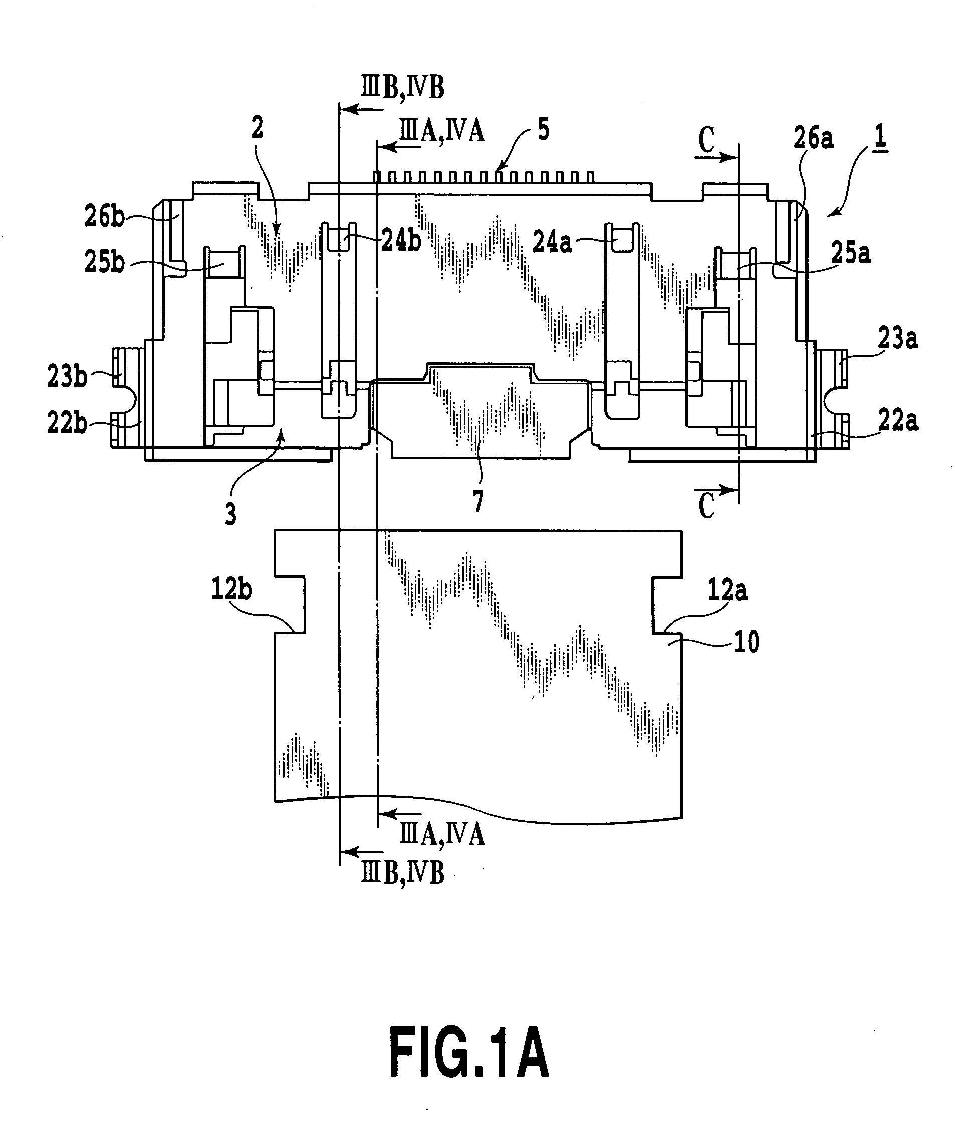
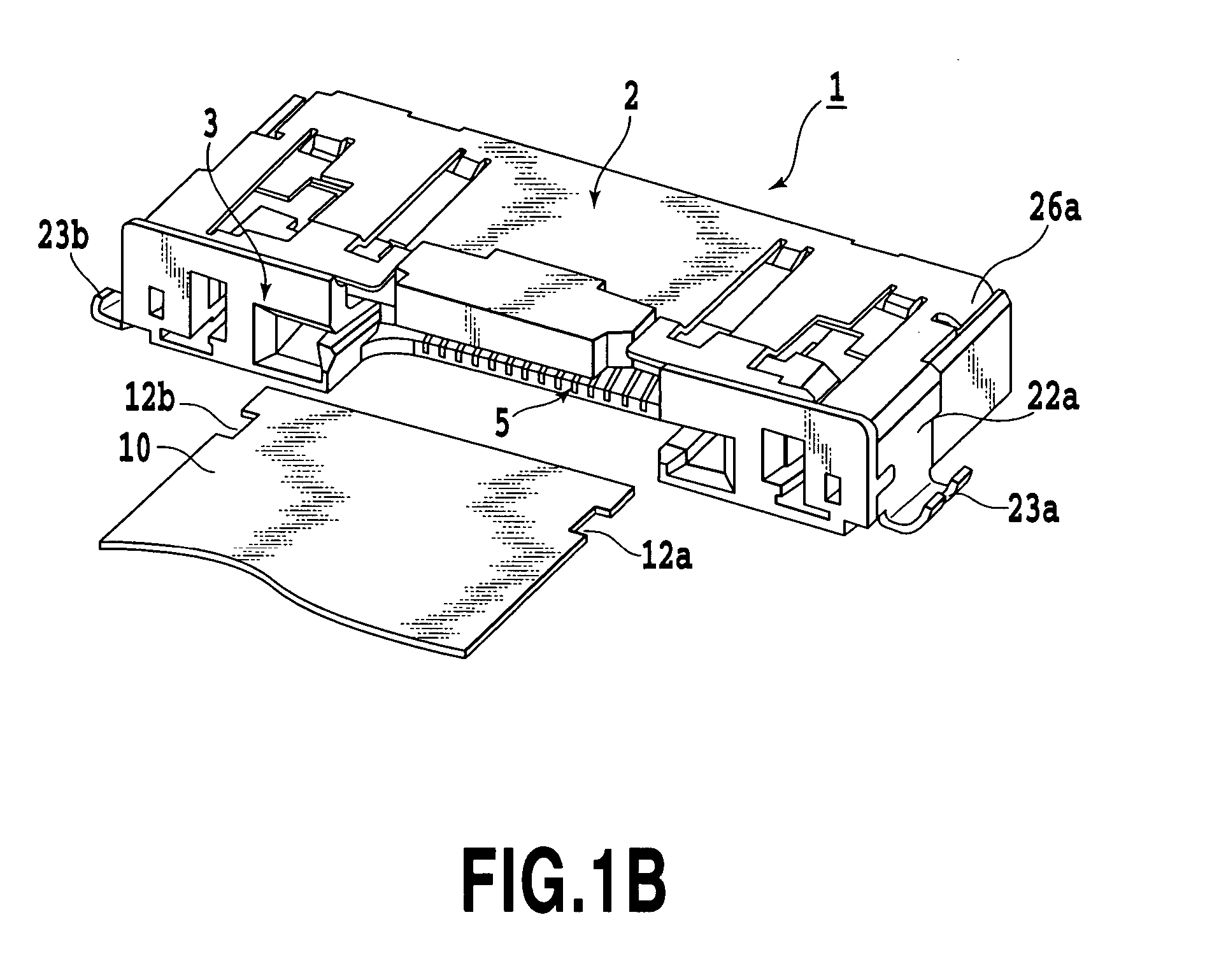
[0035]FIGS. 1A and 1B illustrate the FPC connector in accordance with the present invention, wherein FIG. 1A is an upper view thereof; FIG. 1B is a perspective view thereof; FIG. 2 is a perspective view of a metallic shell of the FPC connector; FIGS. 3A and 3B are sectional views of the FPC connector when the FPC is not inserted, more specifically FIG. 3A is a sectional view taken along a line A-A in FIG. 1A and FIG. 3B is a sectional view taken along a line B-B in FIG. 1A; and FIGS. 4A and 4B are sectional views of the FPC connector similar to FIGS. 3A and 3B when the FPC is inserted, more specifically FIG. 4A is a sectional view taken along a line A-A in FIG. 1A and FIG. 3B is a sectional view taken along a line B-B in FIG. 1A.

[0036] As shown in FIGS. 1A and 1B, the FPC connector in accordance with the present invention generally includes a metallic shell 2, a conne...


PUM


Abstract

An FPC connector having an electromagnetic wave shielding structure improved so that noises do not exceed an allowable value. The FPC connector includes at least a top plate, a metallic shell having left and right walls and a grounding terminal portion, a connector body covered with the metallic shell, a signal line contact, and a grounding contact for grounding the FPC, wherein the metallic shell has a grounding contact partially cut from the top plate and raised the cut portion.

Description

[0001] This application claims priority from Japanese Patent Application Nos. 2003-346284 filed Oct. 3, 2003 and 2004-239954 filed Aug. 19, 2004, which are incorporated hereinto by reference. BACKGROUND OF THE INVENTION [0002] 1. Field of the Invention [0003] The present invention relates to a connector for a flexible printed circuit board for mutually connecting electronic components in electronic apparatuses (hereinafter referred to as an FPC connector), more specifically, to the FPC connector improved for forming a ground contact in the FPC connector for avoiding the interfere of electromagnetic waves with the flexible printed circuit (hereinafter referred to as an FPC). [0004] 2. Description of the Related Art [0005] Up to now, in the FPC connector, part or all of the connector is covered with a metallic shell and the metallic shell and FPC are grounded for shielding the FPC connector from the electromagnetic field as well as suppressing the generation of noise in a signal line ...

Claims


Application Information

Patent Timeline
Patent Type & Authority Applications(United States)
IPC IPC(8): H01R12/79H01R13/652H01R13/648H01R13/658
CPCH01R12/79H01R23/6873H01R13/658
Inventor ENDOU, TOSHIOOOYA, MASAAKIMITHUHASHI, SEIICHIRO
Owner YAMAICHI ELECTRONICS
Why Eureka
Try Eureka