Rocker mechanism

a technology of a rocker and a hammer is applied in the field of a rocker used during orthopedic surgery, which can solve the problems of reducing the use of pliers or levers, reducing the use of hands, and reducing the height between the vertebra

Active Publication Date: 2014-07-15
WILSON GREATBATCH LTD
View PDF33 Cites 9 Cited by
  • Summary
  • Abstract
  • Description
  • Claims
  • Application Information

AI Technical Summary

Benefits of technology

[0015]The right arm of the device forms a handle portion with the opposing left arm. A releasable locking mechanism provides a means for a user to securely grasp the outer surface of the fixation element with the opposing distal end prongs. The locking mechanism comprising a ratchet post and corresponding “V” groove of the proximal end of the left arm enables the prongs to lock ...

Problems solved by technology

Spinal degradation results in the loss of height between the vertebrae.
This loss in height usually results in the pinching of a nerve which routes through the vertebrae, causing pain.
Many times vertebrae are positioned at different elevations and alignments within the body, and as such create complications in establishing proper rod alignment.
In either case, however, neither the use of pliers or levers nor the use of one's hands is optimal.
Pliers for example, are prone to slippage and could easily damage adjacent tissue or bone, particularly when trying to align a rod within pedicle screws, which are at different elevations or angulations.
One's hands may not impart the appropriate forces required to achieve efficacious rod reduction.
However, use of a prior art introducer lever device has not proven advantageous, as the fork tines can be prone not to securely engage with the fixation element.
As such, these prior art rocker tools may slip during rod re...

Method used


Image

  • Rocker mechanism
  • Rocker mechanism
  • Rocker mechanism

Examples


Embodiment Construction

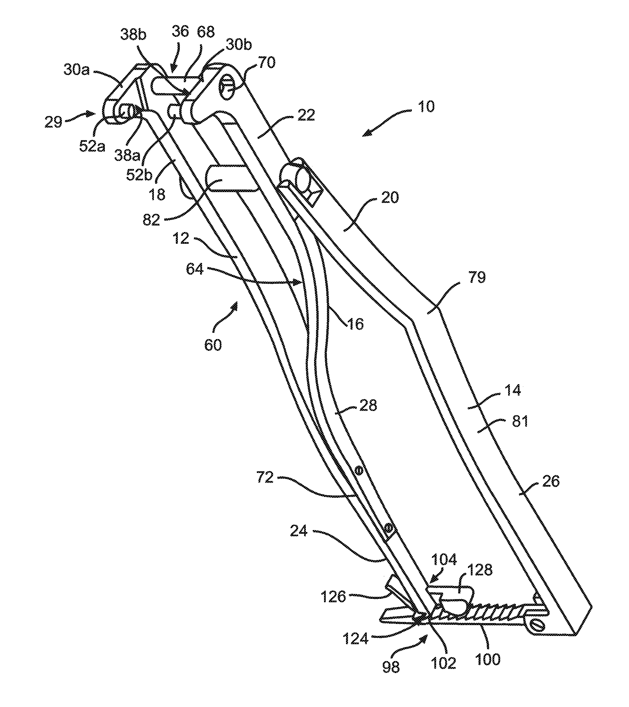
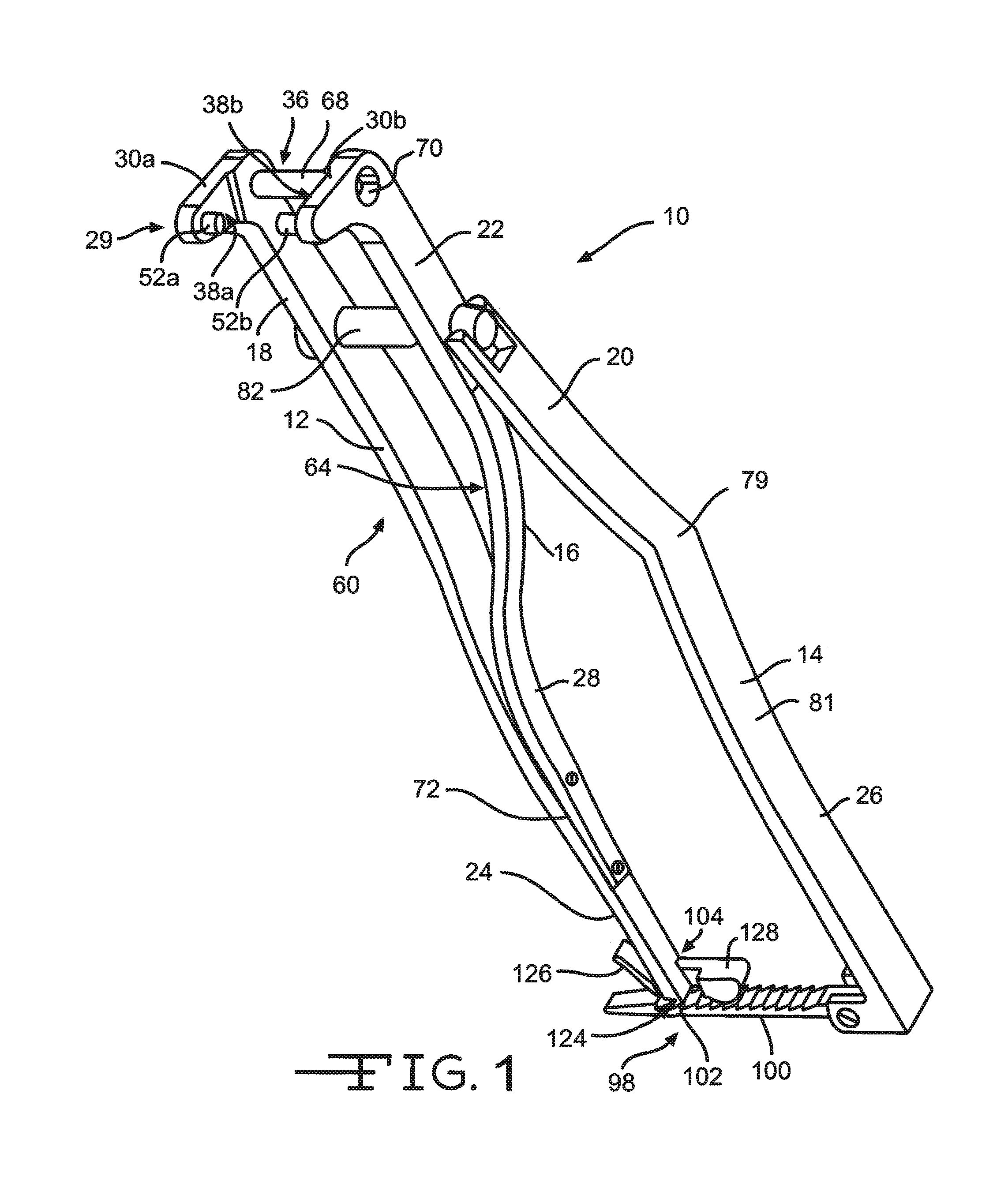
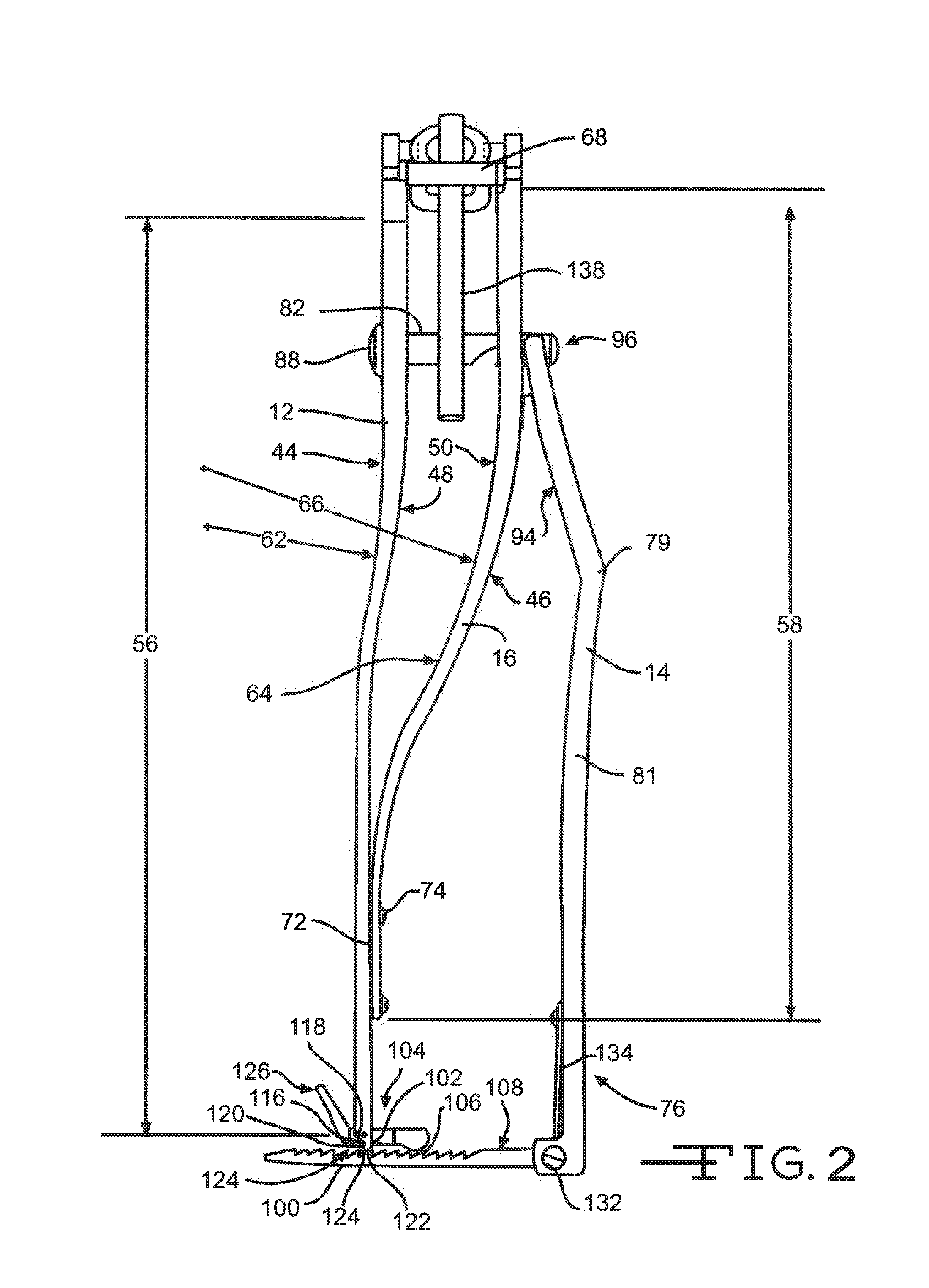
[0023]Now referring to the figures, FIGS. 1-6 illustrate embodiments of an orthopedic instrument 10 of the present invention. As illustrated in FIG. 1, the instrument 10 comprises a left arm 12, a right arm 14, and an intermediary arm 16 positioned therebetween. Each of the arms 12, 14, 16 has a distal end portion 18, 20, 22 separated from a proximal end portion 24, 26, 28. The arms are aligned such that the respective distal end portions 18, 20, 22 and proximal end portions 24, 26, 28, are about parallel to each other. It should be noted that the orthopedic instrument 10 of the present invention can be used with either the user's left or right hand and further can be used in an upwardly or downwardly orientation. The terms “left arm” and “right arm” are used only to identify and distinguish between specific features and embodiments of the present invention. In operation, the “right arm” may in fact be positioned on the left and the “left arm” may be positioned on the right. Further...


PUM


Abstract

An orthopedic instrument designed to engage a rod within a fixation element during a surgical procedure is described. The present invention has a distal end portion designed to hold a fixation element such as a pedicle screw while the rod is positioned within the fixation element. The instrument comprises a series of arms which form the grasping and handle portions of the device.

Description

CROSS-REFERENCE TO RELATED APPLICATION[0001]The present application claims priority from U.S. Provisional Application Ser. No. 61 / 390,462 filed Oct. 6, 2010.BACKGROUND OF THE INVENTION[0002]1. Field of the Invention[0003]The present invention relates to an apparatus used during orthopedic surgery, more particularly, to an instrument used to position an implant during orthopedic spine surgery.[0004]2. Prior Art[0005]In the field of orthopedic surgical procedures, implanting devices that can support bone or tissue to correct deformities or that will position bone and tissue in such a way as to promote healing are well known. In one such procedure, a plurality of fixation elements, such as a pedicle screw, is first positioned within the spine area. Typically, the pedicle screw is first threaded into a pedicle or other portion of vertebral bone in a vertical alignment along a segment of the spinal column. A rod is then positioned between adjoining fixation elements forming an interconne...

Claims


Application Information

Patent Timeline
IPC IPC(8): A61B17/70
CPCA61B17/7085A61B17/7086A61B17/70
Inventor KHALILI, FARID, B.
Owner WILSON GREATBATCH LTD
Why Eureka
Try Eureka