Chaotic approach to control of lighting

a technology of lighting and chaotic system, applied in the direction of electric variable regulation, process and machine control, instruments, etc., can solve the problems of many natural environmental conditions, including natural lighting, chaotic system, negative impact, etc., and achieve the effect of improving controlled lighting

Active Publication Date: 2014-07-15
ABL IP HLDG
View PDF11 Cites 15 Cited by
  • Summary
  • Abstract
  • Description
  • Claims
  • Application Information

AI Technical Summary

Benefits of technology

[0010]The concepts disclosed herein improve controlled lighting by introducing controlled variation of one or more characteristics of light in a chaotic manner.

Problems solved by technology

Many natural environmental conditions, including natural lighting, are chaotic systems.
The impact of the chaotic functional control often is positive; but under some circumstances, the impact may be negative, e.g. to discomfort an unwanted visitor or intruder.

Method used


Image

  • Chaotic approach to control of lighting
  • Chaotic approach to control of lighting
  • Chaotic approach to control of lighting

Examples


Embodiment Construction

[0029]In the following detailed description, numerous specific details are set forth by way of examples in order to provide a thorough understanding of the relevant teachings. However, it should be apparent to those skilled in the art that the present teachings may, be practiced without such details. In other instances, well known methods, procedures, components, and / or circuitry have been described at a relatively high-level, without detail, in order to avoid unnecessarily obscuring aspects of the present teachings.

[0030]The various examples disclosed herein relate to lighting devices, fixtures or systems and ways to control such equipment to provide controlled variation of one or more characteristics of emitted light in a chaotic manner. Reference now is made in detail to the examples illustrated in the accompanying drawings and discussed below.

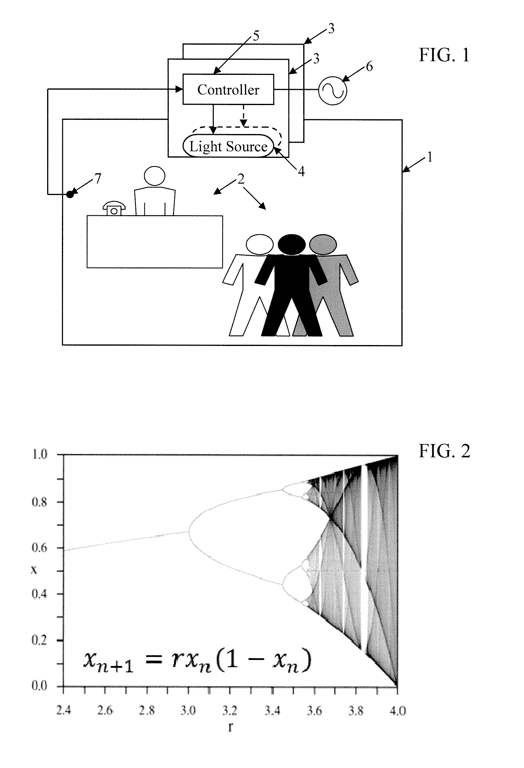
[0031]FIG. 1 illustrates a simple first example. The drawing shows a region or space 1, which is intended to be utilized by one or more oc...


PUM


Abstract

At least one controllable source of visible light is configured to illuminate a space to be utilized by one or more occupants. A controller causes the source(s) to emit light in a manner that varies at least one characteristic of visible light emitted into the space over a period of time at least in part in accordance with a chaotic function.

Description

RELATED APPLICATION[0001]This application is related to U.S. Utility patent application Ser. No. 13 / 594,236 Filed Aug. 24, 2012 entitled “ENVIRONMENTAL CONTROL USING A CHAOTIC FUNCTION,” the disclosure of which is entirely incorporated herein by reference.TECHNICAL FIELD[0002]The present subject matter relates to techniques and equipment to control one or more characteristics of lighting utilizing a chaotic function.BACKGROUND[0003]Electrical lighting has become commonplace in modern society. Electrical lighting devices are commonly deployed, for example, in homes and buildings of commercial and other enterprise establishments. Traditional general lighting devices have tended to be relatively dumb, in that they can be turned ON and OFF, and in some cases may be dimmed, usually in response to user activation of a relatively simple input device. Such lighting devices have also been controlled in response to ambient light detectors that turn on a light only when ambient light is at or ...

Claims


Application Information

Patent Timeline
Patent Type & Authority Patents(United States)
IPC IPC(8): H05B37/02H05B44/00
CPCY02B20/42H05B37/0209H05B37/02H05B33/086H05B37/0245H05B37/029H05B45/20H05B47/175H05B47/155H05B47/11Y02B20/40H05B47/10
Inventor RAMER, DAVID P.RAINS, JR., JACK C.
Owner ABL IP HLDG
Why Eureka
Try Eureka