Control device for lighting LED and detecting breakage thereof

a technology of control device and lamp, which is applied in the direction of electric lighting source, electroluminescent light source, transportation and packaging, etc., can solve the problems of driving at night, inability to show the intention of changing the running direction of the vehicle,

Inactive Publication Date: 2013-09-19
OMRON AUTOMOTIVE ELECTRONICS CO LTD
View PDF4 Cites 5 Cited by
  • Summary
  • Abstract
  • Description
  • Claims
  • Application Information

AI Technical Summary

Benefits of technology

[0027]According to one or more embodiments, by applying this configuration to a device that controls a lamp including a plurality of LEDs in a vehicle, it is possible to provide a control device for lighting an LED and detecting a breakage of the LED, which is capable of controlling the lighting of the plurality of LEDs, and detecting presence or absence of a breakage of each LED, thereby determining which LED is broken, without the necessary for a driver to light the LEDs, for example, upon getting in the vehicle.
[0028]According to one or more embodiments, it is possible to provide a control device for lighting an LED and detecting a breakage of the LED, which is capable of controlling lighting of a plurality of LEDs, and detecting presence or absence of a breakage of each LED, thereby determining which LED is broken, without lighting the LEDs.

Problems solved by technology

If a vehicle lamp, such as a front light, a direction indicator or a stop lamp, is not lighted due to the breakage thereof, the driver has trouble with driving at night or cannot show his / her intention of changing a running direction of the vehicle or stopping it to other surrounding vehicles.

Method used


Image

  • Control device for lighting LED and detecting breakage thereof
  • Control device for lighting LED and detecting breakage thereof
  • Control device for lighting LED and detecting breakage thereof

Examples


first embodiment

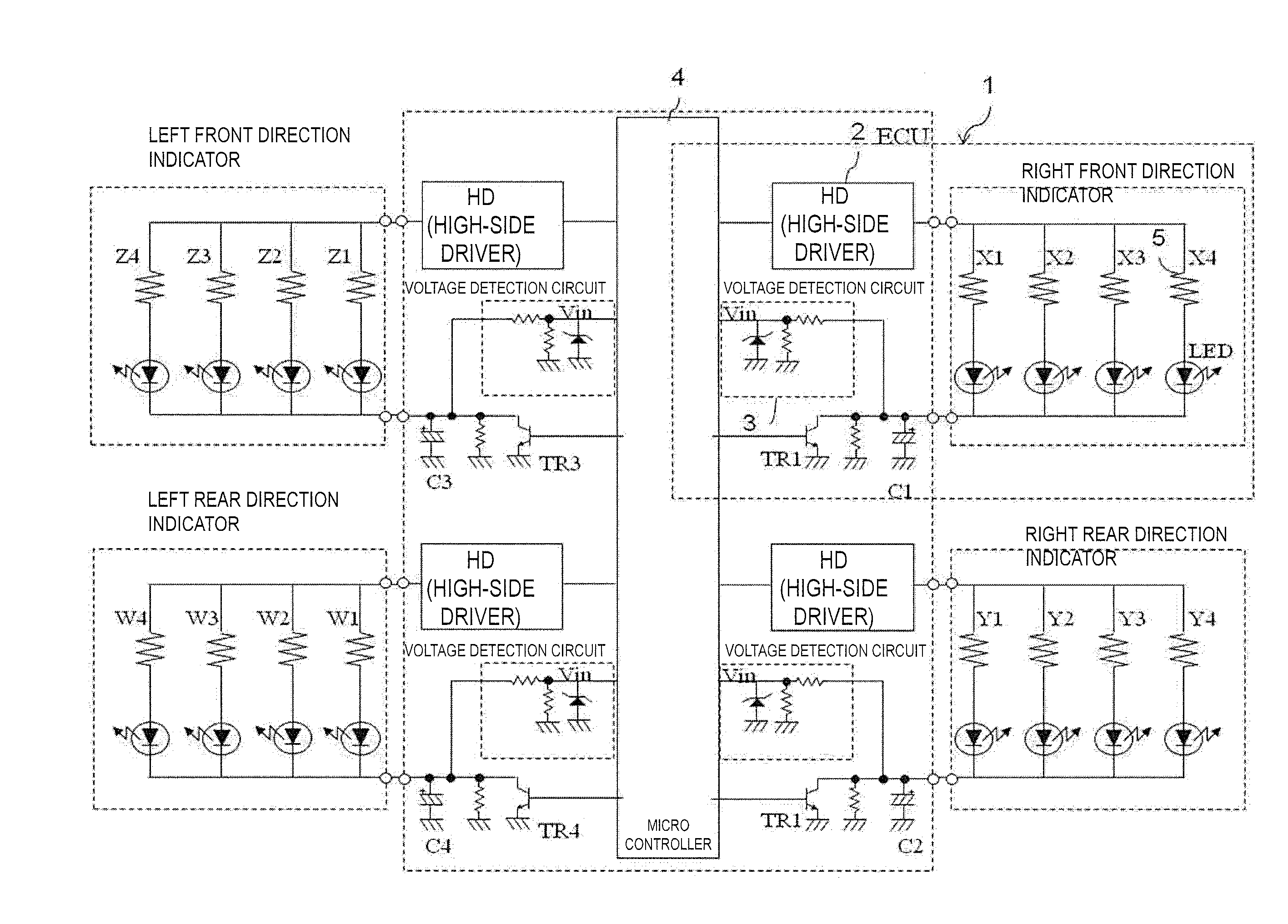
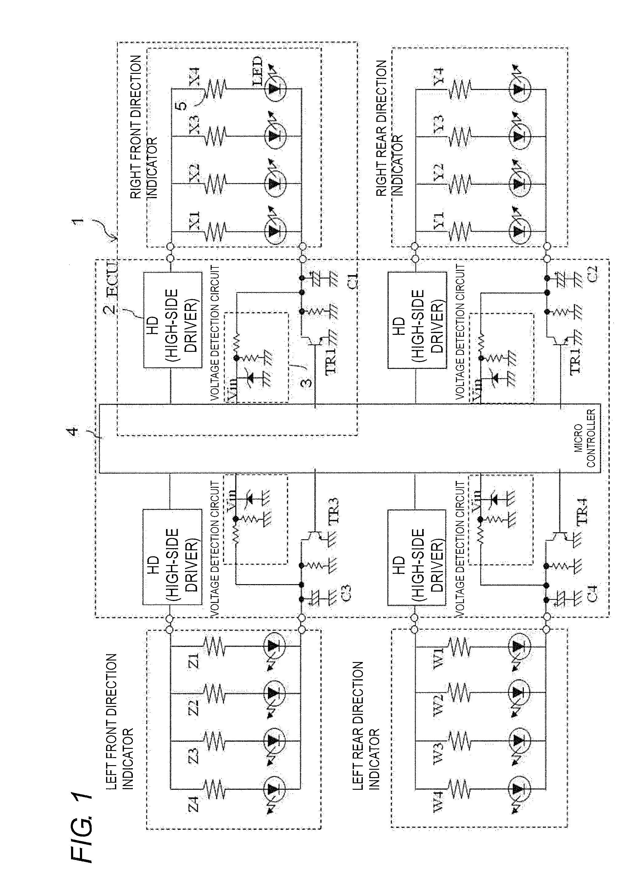
[0037]FIG. 1 is a circuit diagram of control devices 1 according to the first embodiment of the present invention, when the control devices 1 are applied to direction indicators in a vehicle. The control devices 1 are provided corresponding to direction indicators installed at four locations, namely, at a right front, a left front, a right rear, and a left rear of a vehicle. In FIG. 1, the single control device 1 corresponding to the direction indicator at the right front is illustrated, but identical control devices 1 may be arranged corresponding to the direction indicators at the front left, right rear, and left rear. The control device 1 includes, for example, a voltage application circuit 2, a voltage detection circuit 3, and a control circuit 4, and they are provided in an electronic control unit (ECU) of a typical vehicle.

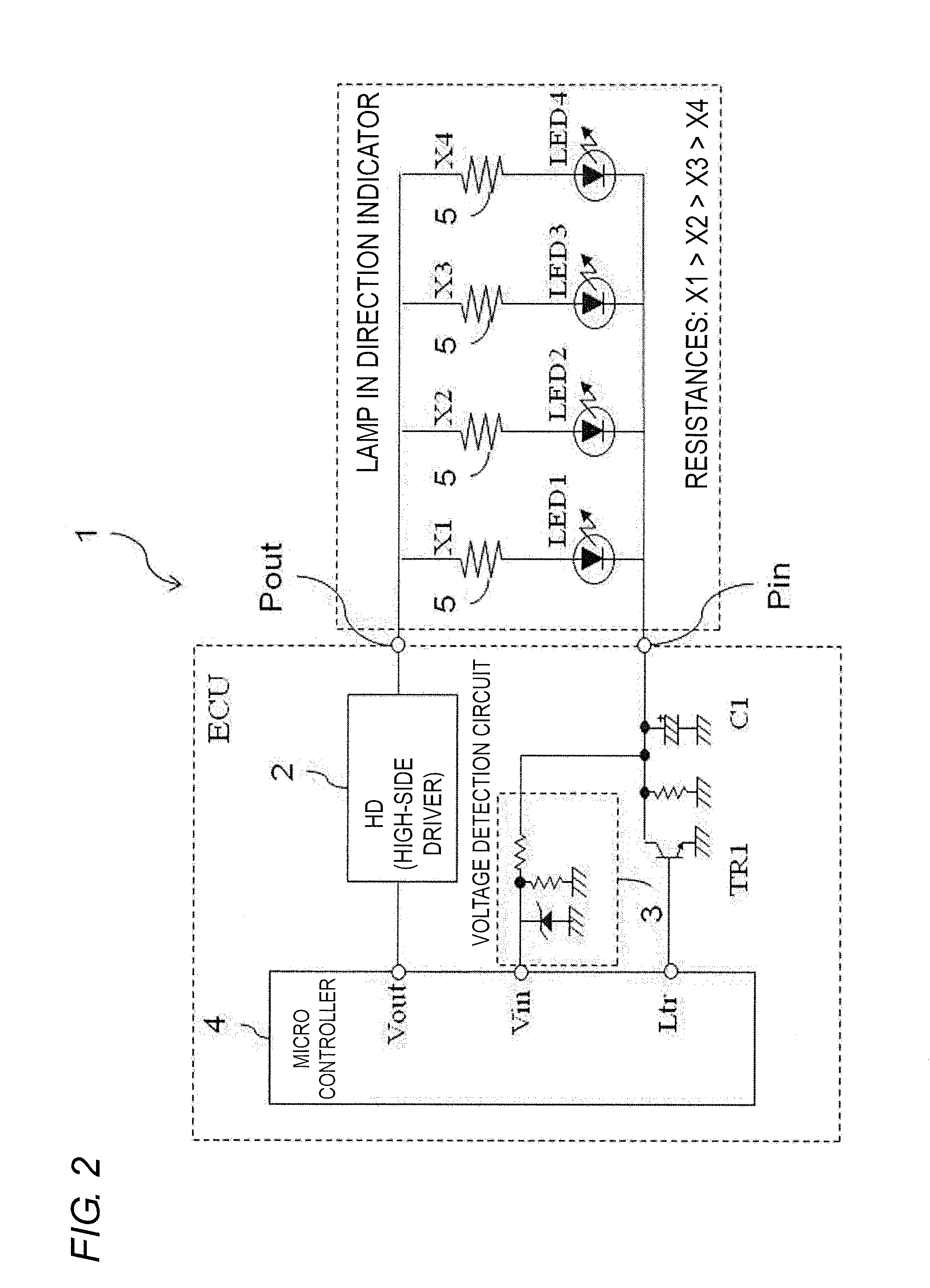
[0038]In FIG. 1, the single control device 1 corresponds to the direction indicator at the right front, and a plurality of LEDs are arranged in this directi...


PUM


Abstract

A control device includes a plurality of LED arrays connected in parallel to one another, each of the plurality of LED arrays including one or more LEDs connected in series and a resistance element connected in series to the LEDs, a voltage application circuit that applies a voltage to the plurality of LED arrays, a switching element disposed between the plurality of LED arrays and a ground, a voltage detection circuit having an end connected between the switching element and the plurality of LED arrays, a capacitor having an end connected between the switching element and the plurality of LED arrays, and another end connected to the ground, and a control circuit that controls the voltage outputted from the voltage application circuit and switching of conduction states of the switching element, and reads a voltage from the voltage detection circuit.

Description

BACKGROUND OF THE INVENTION[0001]1. Technical Field[0002]The present invention relates to a control device for lighting a lamp and detecting a breakage of the lamp, and in particular to a control device for lighting a lamp composed of a light emitting diode (LED) and detecting a breakage of the lamp.[0003]2. Related Art[0004]If a vehicle lamp, such as a front light, a direction indicator or a stop lamp, is not lighted due to the breakage thereof, the driver has trouble with driving at night or cannot show his / her intention of changing a running direction of the vehicle or stopping it to other surrounding vehicles. In order to avoid such troubles, techniques for detecting a breakage of a vehicle light have been contemplated so far. For example, JP 08-332897 A discloses a technique for detecting respective voltages of lighting lamps connected to a control unit, and determining which lamp is broken based on variations in the resistances of the lamps.[0005]On the other hand, lately, LED...

Claims


Application Information

Patent Timeline
Patent Type & Authority Applications(United States)
IPC IPC(8): H05B33/08H05B44/00
CPCH05B33/0827H05B33/089H05B45/46H05B45/50
Inventor SAKUMA, YOICHI
Owner OMRON AUTOMOTIVE ELECTRONICS CO LTD
Why Eureka
Try Eureka