
Mechanical seal device

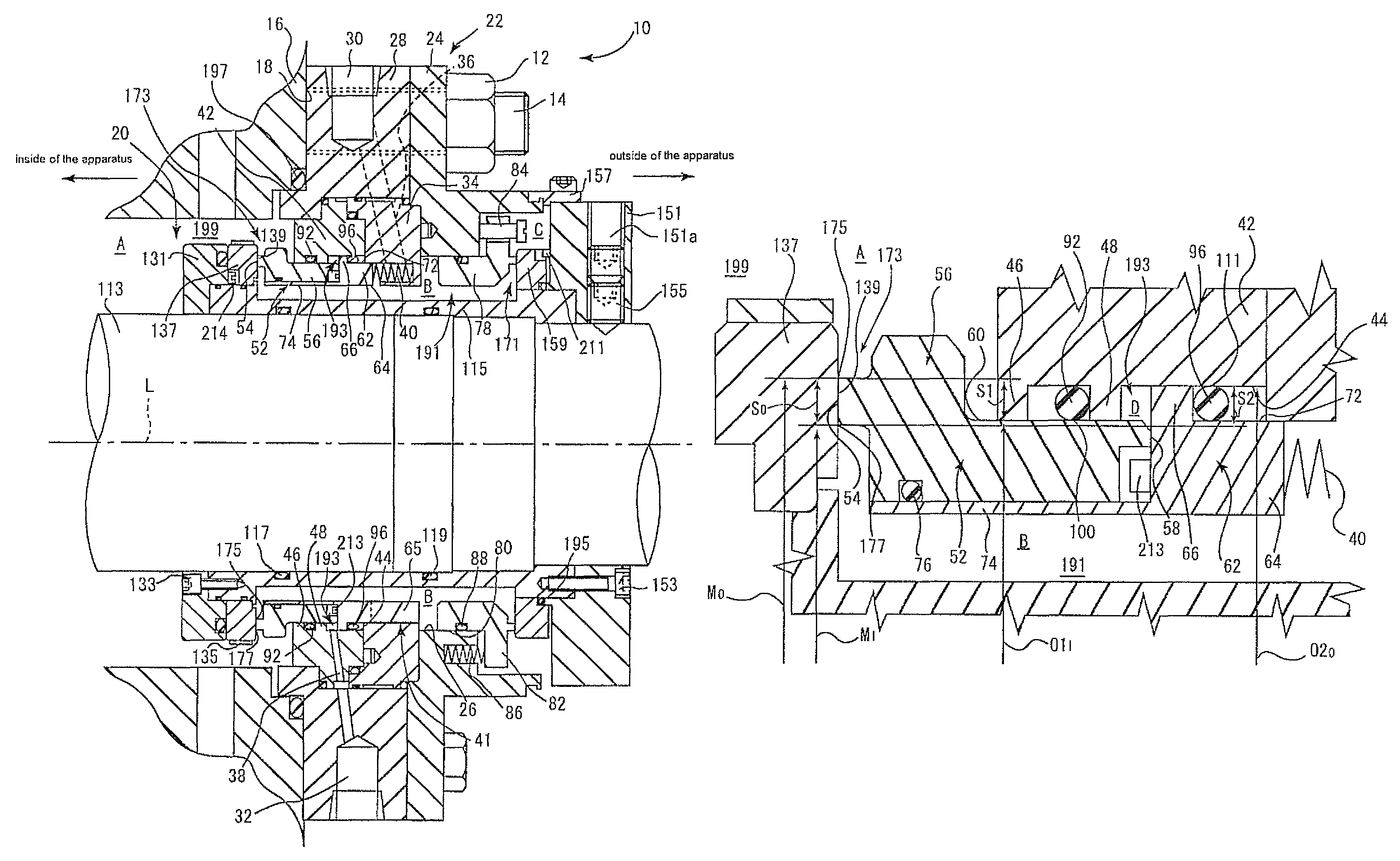
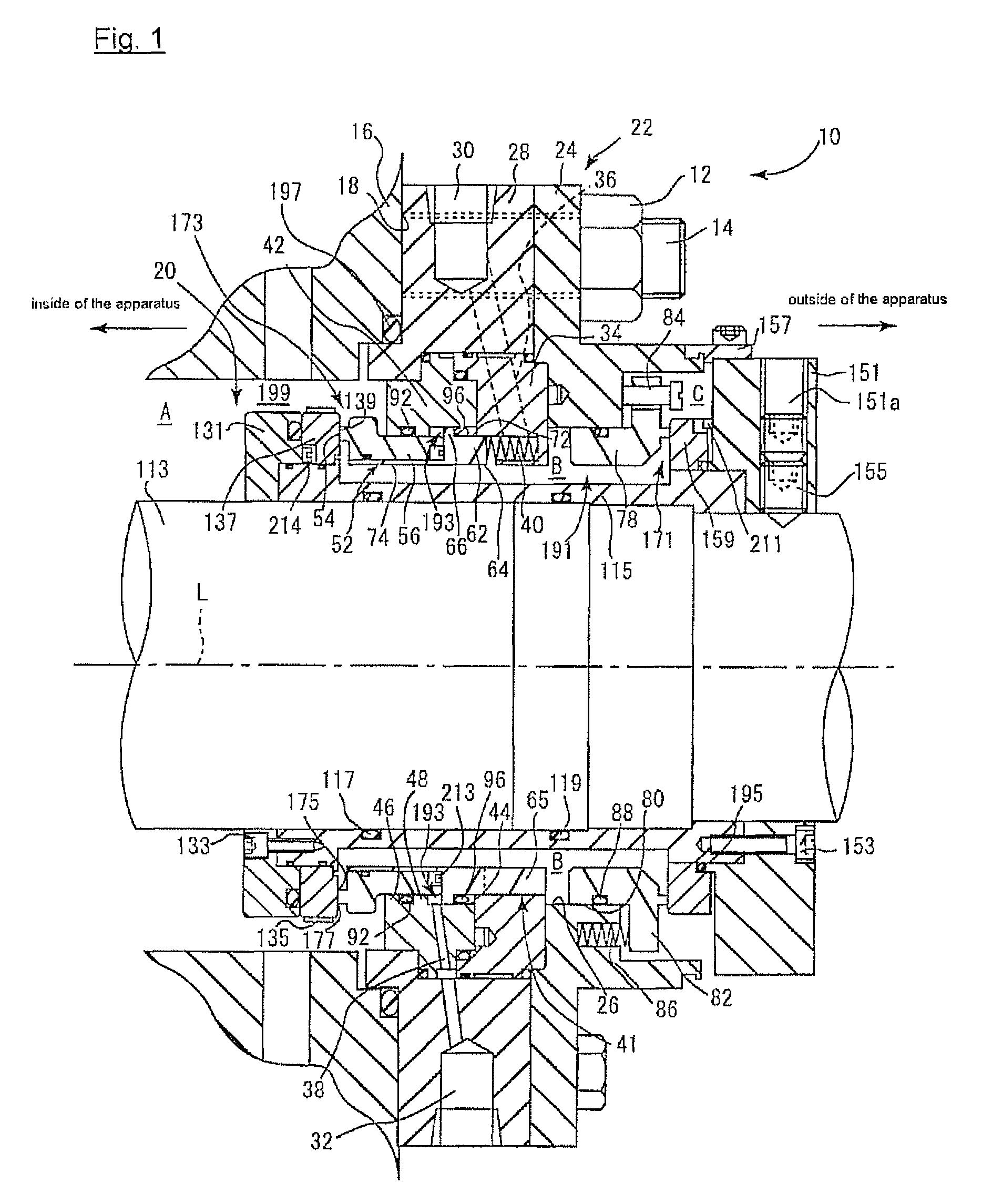
a mechanical seal and sealing device technology, applied in the direction of engine seals, mechanical apparatus, engine components, etc., can solve the problems of reducing the life expectancy o-rings and parts contacting the o-rings are rapidly worn, and problems such as leakage, so as to reduce the type of component parts, simplify the form of low-pressure chamber and the seal cover, and facilitate the assembly of the mechanical seal device

Active Publication Date: 2014-07-22
EAGLE INDS
View PDF9 Cites 2 Cited by
  • Summary
  • Abstract
  • Description
  • Claims
  • Application Information

AI Technical Summary

Benefits of technology

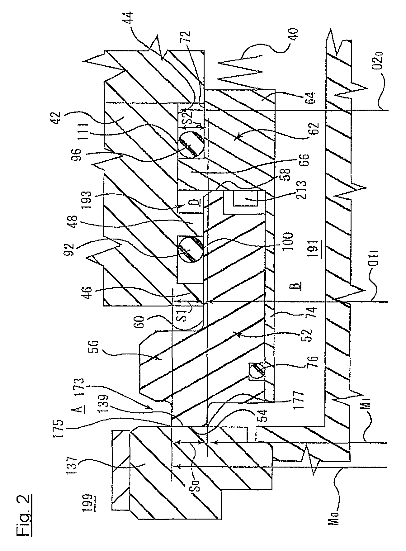
The present invention provides a mechanical seal device that prevents wear and tear of the seal components, such as O-rings, in response to changes in fluid pressure. The device includes a seal cover and a stationary ring assembly, which are connected by two O-rings. The low-pressure chamber formed between the two O-rings prevents wear and tear, even when the fluid pressure switches between positive and counter pressure. This design simplifies the assembly and reduces the likelihood of component parts, making it easier to assemble and maintain. The stationary ring assembly comprises a slide part and an adapter part that are separately formed, simplifying the assembly process. A covering material may be added to the seal cover to improve its assembly and prevent leaks. Overall, the mechanical seal device of the present invention is durable and easy to assemble and disassemble.

Problems solved by technology

Accordingly, a problem occur with the mechanical seal device of conventional art that O-ring itself and stationary ring or step part of housing which contact with O-ring are worn by the movement of O-ring, and reduces life expectancy of the mechanical seal device.
Particularly when used under a condition that fluid pressure frequently switches between positive pressure and counter pressure, O-ring and parts contacting O-ring are rapidly worn; and that problems such as leakage and reduced life expectancy are likely to occur.

Method used


Image

  • Mechanical seal device
  • Mechanical seal device
  • Mechanical seal device

Examples


second embodiment

The Second Embodiment

[0102]FIG. 3 shows a longitudinal sectional view of mechanical seal device 10a according to the second embodiment of the present invention. Mechanical seal device 10a of the second embodiment is the same with mechanical seal device 10 of the first embodiment, except stationary ring assembly within the apparatus 231 and rotary ring within the apparatus 239 both comprise separately formed retainer and slide ring. For the components in mechanical seal device 10a in FIG. 3, which are the same with that of mechanical seal device 10 of the first embodiment, the same reference numerals are given and their explanations are saved.

[0103]Stationary ring assembly within the apparatus 231 of mechanical seal device 10a, as is the same with stationary ring assembly within the apparatus 52 according to the first embodiment, comprises stationary ring slide part 233 and adapter part 62. Stationary ring slide part 233 comprises separately formed stationary slide ring 235 and retai...

third embodiment

The Third Embodiment

[0106]FIG. 4 is a longitudinal cross sectional view of a mechanical seal device 10b as the third embodiment of the present invention. Mechanical seal device 10b of the third embodiment is the same with mechanical seal device 10a of the second embodiment, except stationary slide ring 259 is fixed to retainer at stationary side 271 via the third O-ring 279 and rotary slide ring 275 is fixed to retainer at rotary side 277 via the fourth O-ring 291. For the components in mechanical seal device 10b in FIG. 4, which are the same with that of mechanical seal device 10 of the first embodiment or that of mechanical seal device 10a of the second embodiment, the same reference numerals are given and their explanations are saved.

[0107]Stationary ring assembly within the apparatus 255 of mechanical seal device 10b, as is the same with stationary ring assembly within the apparatus 52 according to the first embodiment, comprises stationary ring slide part 257 and adapter part 6...


PUM


Abstract

A mechanical seal device is provided for use when fluid pressure is frequently switched between positive and counter pressures. A rotary ring is provided on a rotary shaft and a stationary ring assembly is provided on which the stationary ring side sliding face is formed. A seal cover is provided containing the stationary ring assembly on an inner diameter side and supports the freely moving assembly in an axial direction of the rotary shaft along with a first O-ring to seal the first fluid and a second O-ring to seal the second fluid. A low-pressure chamber is sealed from the first fluid and the second fluid and maintains pressure lower than those of the first and the second fluids.

Description

BACKGROUND OF THE INVENTION[0001]1. Field of the Invention[0002]The present invention relates to a mechanical seal device which is preferably used for a shaft seal of centrifugal pump, agitator, etc.[0003]2. Description of the Related Art[0004]There exists a mechanical seal device which seals a high viscosity fluid and the like under a condition that fluid pressure within the apparatus is frequently changed in operation. As for a mechanical seal device used under such condition, for instance, a double mechanical seal device, wherein one O-ring for a secondary seal is sandwiched with a step formed stationary ring and a step formed housing, is known (See Japanese Unexamined Patent Application No. 2003-97728 and the like).[0005]Mechanical seal device of conventional art, comprising the secondary seal O-ring sandwiched between step part of stationary ring and step part of housing, is capable of sealing fluid within the apparatus even when pressure of fluid within the apparatus varies. N...

Claims


Application Information

Patent Timeline
Patent Type & Authority Patents(United States)
IPC IPC(8): F16J15/34F16J15/16F16J15/38
CPCF16J15/3448F16J15/38F16J15/34F16J15/16F16J15/3404F16J15/3436F16J15/3464F16J15/3484
Inventor SUEFUJI, YOSHIHIRO
Owner EAGLE INDS
Learn More