Sealing structure

a sealing structure and sealing technology, applied in the direction of engine seals, mechanical devices, engine components, etc., can solve the problems of large dimensional tolerance becoming a stumbling block for reducing the size of the device, gaskets may not be satisfactorily prevented from dropping or falling in the above-described prior art, and achieve stab installation and installation. stab

Active Publication Date: 2014-07-22
NOK CORP
View PDF22 Cites 8 Cited by
  • Summary
  • Abstract
  • Description
  • Claims
  • Application Information

AI Technical Summary

Benefits of technology

[0034]As described above, according to the present invention, the gasket can be stably installed even if the installation groove has the large dimensional tol

Problems solved by technology

When the installation groove is formed by pressing, it is substantially difficult to form the groove into a rectangular shape in cross section.
The large dimensional tolerance becomes a stumbling block for reducing the size of the device when the installation groove is formed by pressing.
In such a situation that the dimensi

Method used


Image

  • Sealing structure
  • Sealing structure
  • Sealing structure

Examples


first embodiment

[0053](First Embodiment)

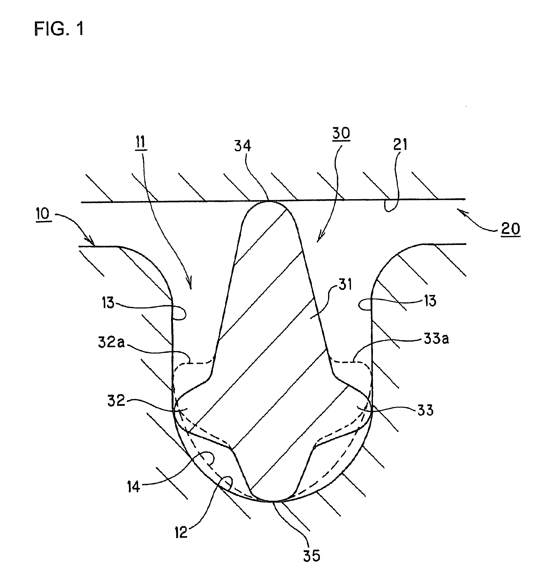
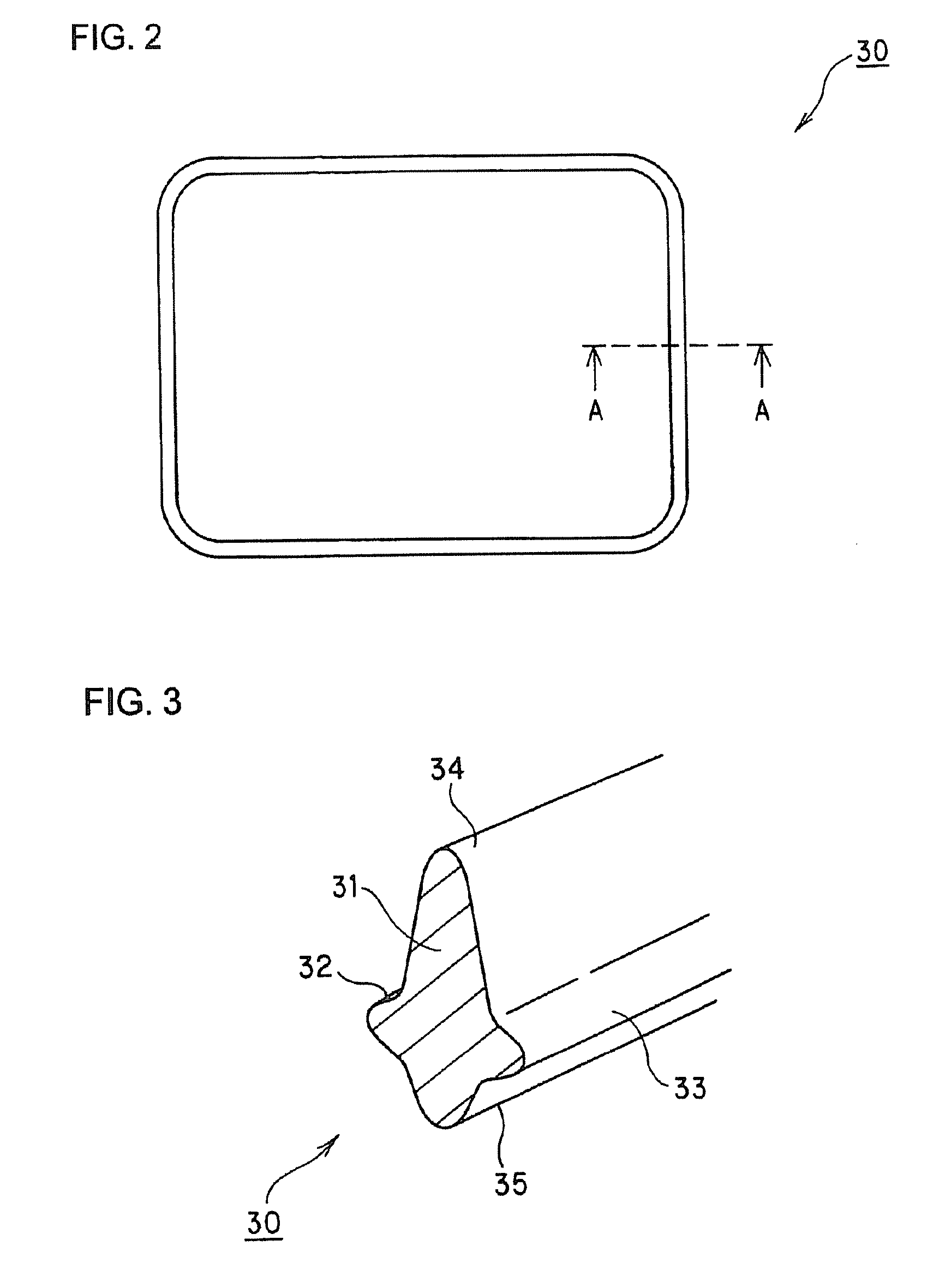
[0054]Referring to FIGS. 1 to 3, a sealing structure in a first embodiment according to the present invention will be described. FIG. 1 is a cross-sectional view schematically showing a sealing structure in a first embodiment according to the present invention; FIG. 2 is a plan view showing a gasket in the first embodiment according to the present invention; and FIG. 3 is a perspective view schematically showing the gasket in the first embodiment according to the present invention.

[0055]

[0056]The sealing structure in the present embodiment is designed to seal a clearance defined between two members (one member 10 and the other member 20) with a gasket 30. One member 10 and the other member 20 are to be assembled each other by not-shown means (for example, well known means such as fitting, screwing, or bonding). FIG. 1 shows a state before one member 10 and the other member 20 are assembled each other.

[0057]Although a state in which the members are assembled e...

second embodiment

[0078](Second Embodiment)

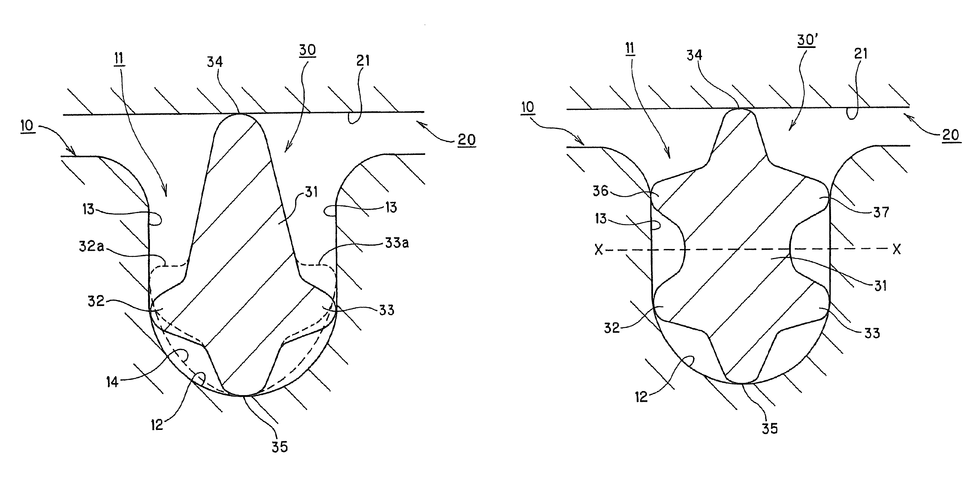
[0079]Next, a second embodiment according to the present invention will be described below with reference to FIG. 4. FIG. 4 is a cross-sectional view schematically showing a sealing structure in a second embodiment according to the present invention. In a sealing structure in the present embodiment, a pair of projections 36 and 37 for preventing the gasket 30 from falling is additionally formed near the opening of the installation groove 11 in the gasket 30 in the first embodiment. The other configuration and function are identical to those in the first embodiment, and therefore, the same constituents are designated by the same reference numerals, and their description will not be repeated below.

[0080]A gasket 30′ in the present embodiment is provided with the pair of projections 36 and 37 projecting from side surfaces in a body section 31 near an opening of an installation groove 11 toward both sides in a widthwise direction. In this manner, the pair of pro...

third embodiment

[0085](Third Embodiment)

[0086]Subsequently, a third embodiment according to the present invention will be described below with reference to FIG. 5. FIG. 5 is a cross-sectional view schematically showing a sealing device in a third embodiment according to the present invention. In a sealing device in the present embodiment, side surfaces 13 are inclined such that the groove width of the installation groove 11 is enlarged from the groove bottom side toward the opening side in the above-described embodiments. The other configuration and function are identical to those in the above-described embodiments, and therefore, the same constituents are designated by the same reference numerals, and their description will not be repeated below.

[0087]If the machining precision of an installation groove is reduced in order to reduce a fabrication cost, the installation groove may be formed into a shape shown in FIG. 5. Specifically, an installation groove 11′ is formed in such a manner that its gr...


PUM


Abstract

A sealing structure having a gasket installed in an installation groove in one member. The gasket has a body section whose width is less than the width of the installation groove. On opposite ends, in the depth direction of the installation groove, there is provided a pair of seal surfaces that contact a surface of another member and the bottom of the installation groove. The bottom surface of the installation groove is a curve that is deepest at its center in the width direction of the groove. On the gasket body section, on the side corresponding to the bottom of the installation groove, there is formed a pair of groove bottom-side projections extending along the longitudinal direction of the gasket with the seal surface between the projections, projecting from opposite ends in the width direction of the body section, and coming into contact with the surface of the installation groove.

Description

FIELD OF THE INVENTION[0001]The present invention relates to a sealing structure for sealing a clearance defined between two members with a gasket.BACKGROUND OF THE INVENTION[0002]Various kinds of sealing devices such as a gasket and a packing have been conventionally known as devices for sealing a clearance defined between two members. They have been formed into various shapes. Moreover, there have been a variety of sealing structures in which the sealing devices are used.[0003]Patent Document 1, for example, discloses a sealing structure, in which a bottom side of a gasket is suppressed from sliding sideways of a installation groove by curving a bottom of the installation groove, so as to prevent the gasket from falling down, and further, the gasket can be installed irrespective of the obverse and reverse thereof by forming the gasket into a symmetric shape in cross section.[0004]Otherwise, Patent Document 2 discloses a packing for an injector, in which projections are formed on b...

Claims


Application Information

Patent Timeline
IPC IPC(8): F16J15/02
CPCF16J15/025F16J15/106
Inventor MATSUO, TAKESHI
Owner NOK CORP
Why Eureka
Try Eureka