Telecommunications networks

a technology of telecommunications networks and information indicators, applied in the field of telecommunications networks, can solve the problem that the system information indicator alone is not sufficient to enable the mobile to (fully) access the telecommunications system, and achieve the effect of freeing up radio capacity and bandwidth required for transmission

Active Publication Date: 2014-07-22
VODAFONE GRP PLC
View PDF8 Cites 0 Cited by
  • Summary
  • Abstract
  • Description
  • Claims
  • Application Information

AI Technical Summary

Benefits of technology

[0022]In the embodiments the system information indicator is broadcast by the cell on the BCH. Because the system information indicator contains less data than the system information conventionally transmitted on the BCH, the amount of data transmitted in the BCH according to the embodiments of the invention is much reduced compared to the prior art. Therefore, even if the periodicity (frequency) with which the BCH is transmitted is maintained, in the embodiments of the invention, the bandwidth required to transmit the BCH data to all mobile terminals in the cell is significantly reduced, thereby freeing up radio capacity for other purposes.

Problems solved by technology

In the embodiments to be described in detail the system information indicator alone is insufficient to enable the mobile to (fully) access the telecommunications system.

Method used


Image

  • Telecommunications networks
  • Telecommunications networks
  • Telecommunications networks

Examples


first embodiment

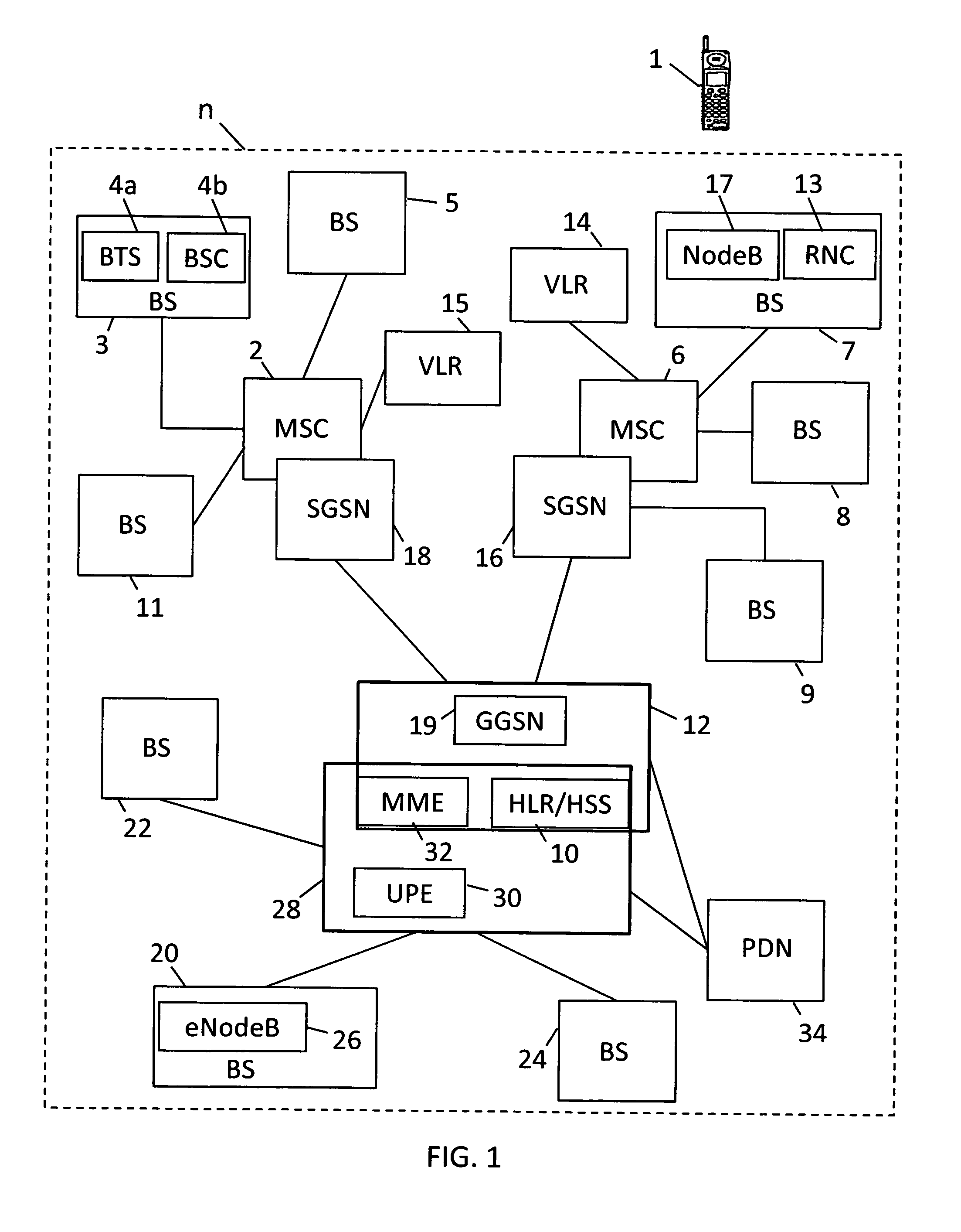
[0070]the system described herein will now be described with reference to FIG. 2.

[0071]In contrast to the prior art, not all the system parameters for allowing the mobile terminal 1 to access the cell in which it is located are transmitted on the BCH. Instead, the BCH transmits (only) a system information indicator, which in this embodiment comprises a system information minimum set. The system information minimum set is transmitted by the eNode B 26 of the base station 20 that serves the cell in which the mobile terminal 1 is located, in message A of FIG. 2. This system information minimum set only includes a sub-set of the information that is conventionally transmitted on the BCH. The system information minimum set includes the identifier of the network (n), PLMN ID, and the tracking area, TA, in which the cell is located, and information to find the RACH and to configure access to the RACH.

[0072]After receiving the system information minimum set in message A, the mobile terminal ...

third embodiment

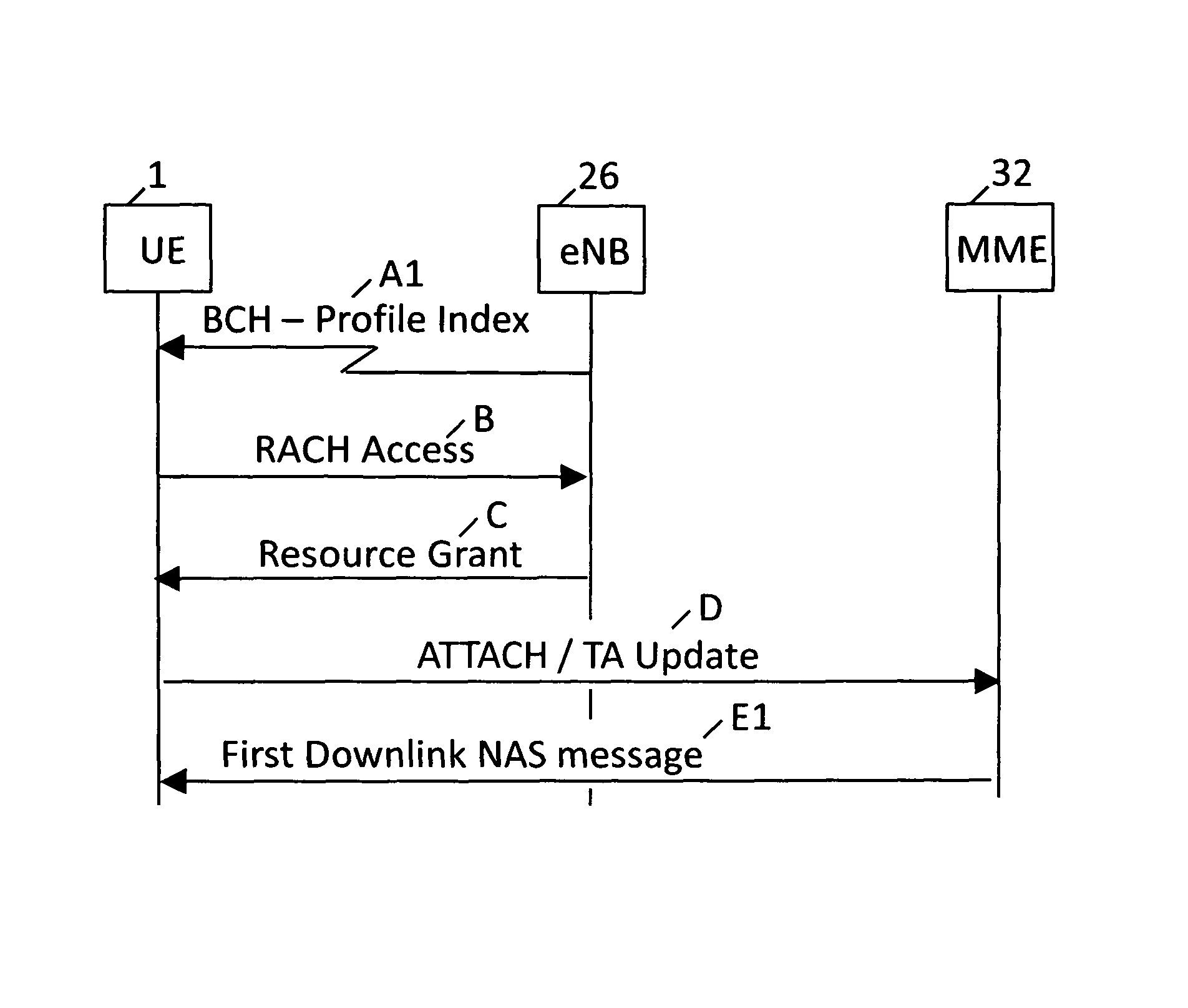
[0078]In the third embodiment the mobile terminal 1, shown in more detail in FIG. 4, includes a system information profiles store 36 which stores a plurality of system information profiles, SI 1, SI 2, SI 3, SI 4, . . . , SI n. The value (1 . . . n) following “SI” is the system information profile index number of each of the system information profiles in the store 36. The system information profiles may be stored on the mobile terminal 1 during its manufacture, or may be uploaded to the mobile terminal 1 by over the air (OTA) transmission by the system (n). System information profiles stored on the mobile terminal 1 (whether by being pre-stored when the mobile terminal is manufactured, or uploaded to the mobile terminal by the system (n)), can be reconfigured by the system operator by OTA transmissions—that is, elements of each system information profile can be varied, without necessarily transmitting the whole systems information profile. For example, any changes to the system inf...


PUM


Abstract

Providing a mobile terminal with system information which enables the terminal to access one of the cells of a cellular telecommunications system includes transmitting from the telecommunications system to all terminals within the cell, including the terminal, a system information indicator that makes available to the terminal system information to provide access to the system. The system information indicator is transmitted on the broadcast channel (BCH). The system information indicator may be a sub-set of the system information conventionally transmitted on the BCH but which is sufficient to allow the mobile terminal to access the network and obtain in the downlink further system information. Alternatively, the information transmitted in the BCH may be a profile index value which directs the mobile terminal to retrieve from a store of the mobile terminal system information pre-stored on the mobile terminal.

Description

TECHNICAL FIELD[0001]This application relates to a method of providing a terminal with system information which enables the terminal to access one of the cells of a cellular system, and to a telecommunications system for implementing this method.BACKGROUND TO THE INVENTION[0002]2G (GSM) and 3G (UMTS / UTRA) mobile telecommunications networks have a radio interface in which user data and signalling may be sent either on a dedicated channel (DCH) allocated to a particular mobile terminal (for a given service offered to the mobile terminal) or on a common channel. Common channels include the random access channel (RACH), forward link access channel (FACH), broadcast channel (BCH) and the paging channel (PCH).[0003]The RACH is used only in the uplink direction. Because the RACH is not reserved, there is a risk that multiple mobile terminals will use it simultaneously so that a “collision” occurs on the radio path and data cannot be successfully received by the network. When using the RACH...

Claims


Application Information

Patent Timeline
Patent Type & Authority Patents(United States)
IPC IPC(8): H04W48/12H04H20/71
CPCH04W48/12H04W48/16
Inventor FOX, DAVID
Owner VODAFONE GRP PLC
Why Eureka
Try Eureka