Communications terminal and method

a technology of communication terminals and terminals, applied in the field of mobile communications networks, can solve problems such as interface congestion, and achieve the effects of reducing the bandwidth of reducing the burden on the interface, and reducing the congestion on the interface between the serving base station and the co-operating base station

Active Publication Date: 2017-01-31
IPLA HLDG
View PDF14 Cites 0 Cited by
  • Summary
  • Abstract
  • Description
  • Claims
  • Application Information

AI Technical Summary

Benefits of technology

[0007]According to an aspect of the present invention there is provided a mobile communications network for communicating data to and / or from one or more communications terminals. The mobile communications network comprises a core network part including infrastructure equipment, and a radio network part including a plurality of base stations which are configured to provide a wireless access interface for communicating the data to or from the communications terminals. One of the plurality of base stations is configured to operate as a serving base station to one of the communications terminals, to establish in co-operation with the communications terminal one or more communications bearers for communicating user data to or from the communications terminal via the core network part and the radio network part via the serving base station, and to co-operate with at least one other of the plurality of base stations to communicate the user data to or from the communications terminal. The co-operating base station is configured to receive user data for communicating to the communications terminal via an interface between the serving base station and the co-operating base station, and to transmit the user data selectively to the communications terminal consequent upon a state of a radio communications channel established via the wireless access interface under the control of the serving base station. The mobile communications network is configured to monitor a state of the radio communications channel between the co-operating base station and the communications terminal, and consequent upon predetermined conditions, to establish a communications bearer from the core network to the co-operating base station for communicating the user data to the co-operating base station for transmitting the user data to the communications terminal. Accordingly, a bandwidth requirement of the interface between the serving base station and the co-operating base station can be reduced.
[0010]Embodiments of the present invention have therefore been devised so as to reduce and to relieve a burden on the interface between the base stations of a co-operating set of base stations. Accordingly depending on predetermined conditions being satisfied, which can include a state of the radio link between the co-operating base station and the communications terminal provided by the wireless access interface, embodiments of the present invention are arranged to establish a communications bearer from the core network to the co-operating base station (referred to for brevity as a sub-bearer) for communicating the user data to the co-operating base station without going through the serving base station. Therefore, there can be no need to communicate the user data on the interface between the serving base station and the co-operating base station and accordingly congestion on the interface between the serving base station and the co-operating base station is reduced. As will be appreciated, if many communications terminals are being served by a co-operating set of base stations then by providing a separate communications bearer from the core network to each of the co-operating base stations for communicating the user data to the co-operating base stations rather than only the serving base station then a bandwidth of the interface between the serving base station and the co-operating base stations can be reduced. The interface can then be used to communicate scheduling assignments for the communication of the user data from the co-operating set of base stations in accordance with the radio communications channel as would be performed conventionally. Therefore in some embodiments, after the communications bearer between the serving gateway and the co-operating base stations has been established, the serving base station may stop transmitting the user data of the selected communications bearer via the interface between the serving base station and the co-operating base station.

Problems solved by technology

However if there are many mobile stations which are transmitting or receiving data using the same co-operating set of base stations then because the interface between the serving base station and the co-operating base station (X2 interface) must carry scheduling assignments for transmitting the user data, control information as well as the user data to be communicated then the interface can become congested because of a limited bandwidth of the interface which is available.

Method used


Image

  • Communications terminal and method
  • Communications terminal and method
  • Communications terminal and method

Examples


Embodiment Construction

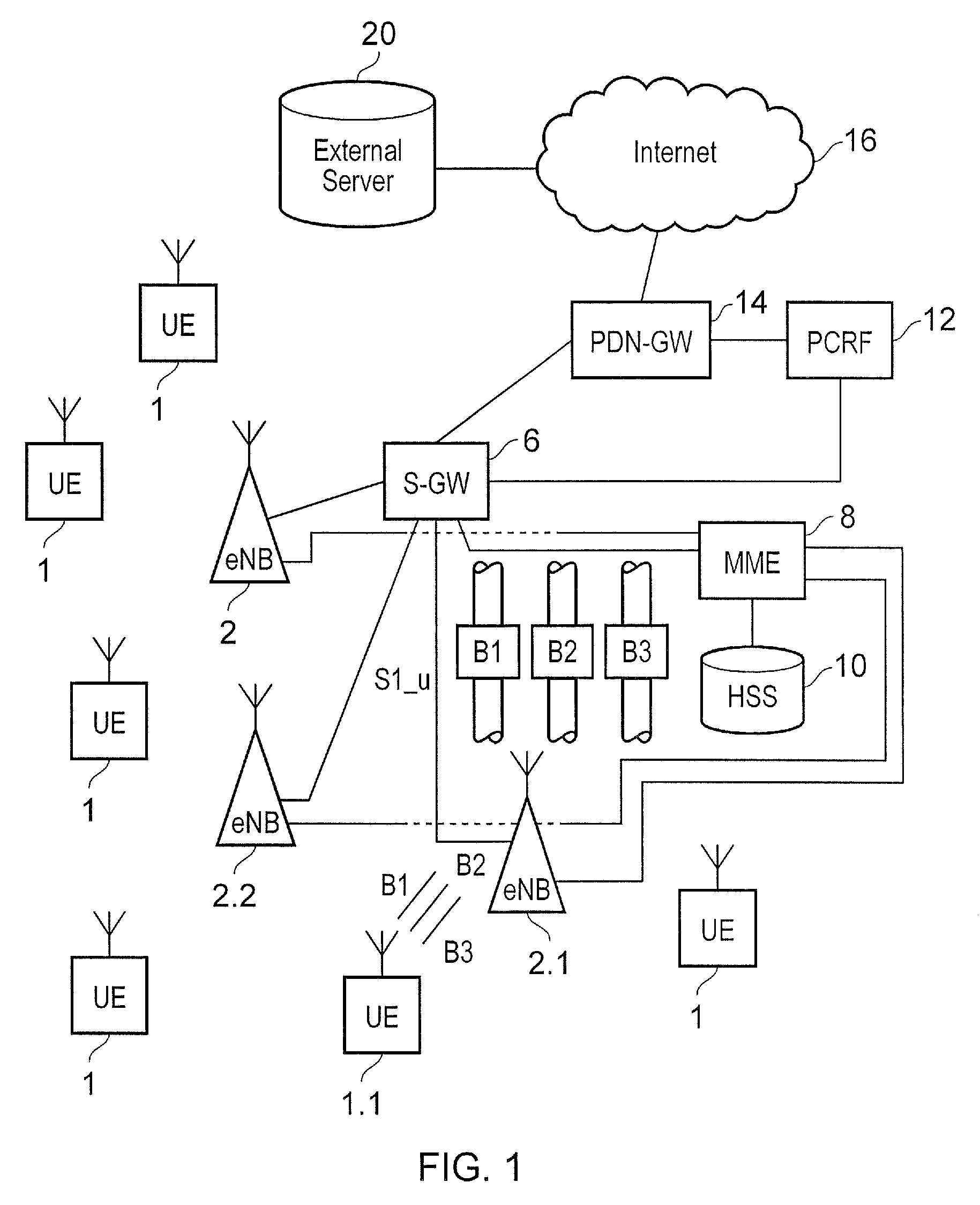
[0022]Embodiments of the present invention will now be described with reference to an implementation which uses a mobile communications network operating in accordance with the 3GPP Long Term Evolution (LTE) standard. FIG. 1 provides the example architecture of an LTE network. As shown in FIG. 1 and as with a conventional mobile communications network, communications terminals (UE) 1 are arranged to communicate data to and from base stations 2 which are referred to in LTE as enhanced NodeBs (eNB). For transmitting and receiving data via the wireless access interface the communications terminals 1 each include a transmitter / receiver unit 3.

[0023]The base stations or eNB's 2 are connected to a serving gateway S-GW 6 which is arranged to perform routing and management of mobile communications services to the communications terminals 1 as they roam throughout the mobile radio network. In order to maintain mobility management and connectivity, a mobility management entity (MME) 8 manages...


PUM


Abstract

A mobile communications network includes a core network including infrastructure equipment, and a radio network including plural base stations configured to provide a wireless access interface for communicating data to / from communications terminals. One base station can operate as a serving base station to one of the communications terminals, to establish one or more communications bearers for communicating user data to / from the communications terminal via the core network and the radio network, and co-operate with at least another of the base stations to communicate the user data to / from the communications terminal. The mobile communications network can monitor a state of a radio communications channel between the co-operating base station and the communications terminal, and upon predetermined conditions, establish a communications bearer from the core network to the co-operating base station for communicating the user data to the co-operating base station for transmitting the user data to the communications terminal.

Description

CROSS-REFERENCE TO RELATED APPLICATIONS[0001]The present application is based on PCT filing PCT / GB2013 / 050168 filed Jan. 25, 2013, and claims priority to British Patent Application 1201659.8, filed in the UK IPO on 31 Jan. 2012 and British Patent Application 1201658.0, filed in the UK IPO on Jan. 31, 2012, the entire contents of each of which being incorporated herein by reference.FIELD OF THE INVENTION[0002]The present invention relates to mobile communications networks for communicating data to and / or from communications terminals, infrastructure equipment, communications terminals and methods of communicating.BACKGROUND OF THE INVENTION[0003]Mobile communication systems have evolved over the past ten years or so from the GSM System (Global System for Mobiles) to the 3G system and now include packet data communications as well as circuit switched communications. The third generation project partnership (3GPP) has now began to develop a mobile communication system referred to as Lo...

Claims


Application Information

Patent Timeline
Patent Type & Authority Patents(United States)
IPC IPC(8): H04W4/00H04L5/00H04W76/02H04W24/08H04W72/04H04W72/08H04W16/24H04W36/28H04W36/18H04W92/20H04W88/02
CPCH04L5/0032H04W16/24H04W24/08H04W72/04H04W72/042H04W72/085H04W76/02H04W76/025H04W36/18H04W36/28H04W88/02H04W92/20H04W76/15H04W76/10H04W24/00H04W28/16H04W72/23H04W72/542
Inventor ZAKRZEWSKI, ROBERTTESANOVIC, MILOS
Owner IPLA HLDG
Why Eureka
Try Eureka