Supercharge Your Innovation With Domain-Expert AI Agents!

Slat configuration for fixed-wing aircraft

a fixed-wing aircraft and configuration technology, applied in aircraft control, aircraft components, wing adjustments, etc., can solve the problems of delayed stall onset and insufficient wing maximum lift, so as to improve the slat configuration, delay the onset of stall, and the maximum lift is greater

Active Publication Date: 2014-07-29
BOMBARDIER INC
View PDF13 Cites 3 Cited by
  • Summary
  • Abstract
  • Description
  • Claims
  • Application Information

AI Technical Summary

Benefits of technology

This configuration increases the maximum lift coefficient and delays stall onset by 2 to 4 degrees, improving aircraft performance during take-offs and landings without adding complexity or weight, validated through theoretical and experimental methods.

Problems solved by technology

These configurations, however, do not provide the wing maximum lift and delayed stall onset that the embodiments of the present invention provide.

Method used


Image

  • Slat configuration for fixed-wing aircraft
  • Slat configuration for fixed-wing aircraft
  • Slat configuration for fixed-wing aircraft

Examples


Embodiment Construction

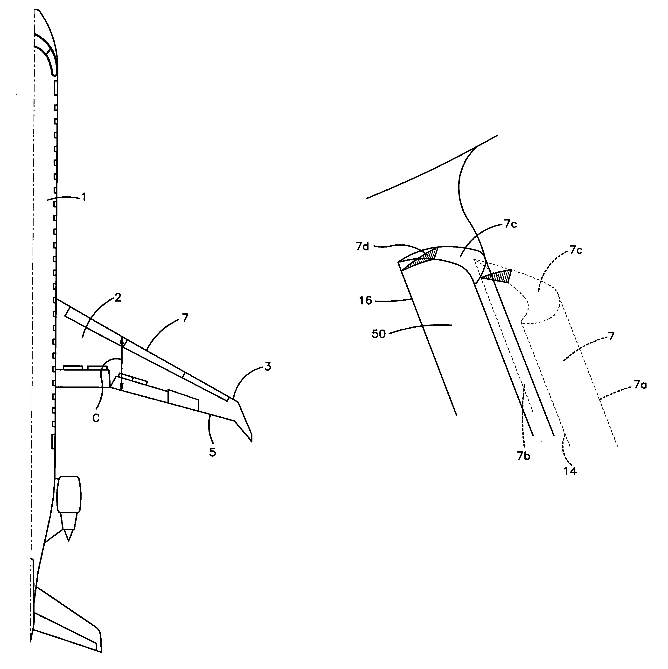
[0008]For the reasons provided above, it is an object of an embodiment of the present invention to have an improved slat configuration for a fixed-wing aircraft that achieves greater maximum lift and delays stall onset. Such an objective is attained by providing a slat that includes a leading edge, a trailing edge, a chord and an inboard edge that further includes a first leg that extends from the leading edge and a second leg that extends from the first leg to the trailing edge. In this embodiment, the first leg of the inboard edge extends straight to the trailing edge for at least 40% of the chord.

[0009]Another object of an embodiment of the present invention is to provide a slat that includes a leading edge, a trailing edge, a chord and an inboard edge that includes a first leg that extends from the leading edge and a second leg that extends from the first leg to the trailing edge. In this embodiment, the first leg extends straight to the trailing edge for no more than 90% of the...


PUM


Abstract

A slat for fixed-wing aircraft that includes a leading edge, a trailing edge, a chord, and an inboard edge that includes particular dimensions to affect airflow over the wing.

Description

CROSS-REFERENCE TO RELATED APPLICATION(S)[0001]This is a National Stage Entry into the United States Patent and Trademark Office from International PCT Patent Application No. PCT / IB2008 / 000311, having an international filing date of 12 Feb. 2008, the contents of which is incorporated herein by reference.FIELD OF INVENTION[0002]The embodiments of the present invention are directed to slats located on the leading edge of wings for fixed-wing aircraft. More specifically, the embodiments of the present invention are directed to the particular configuration of the inboard edge of such slats.STATEMENT RE FEDERALLY SPONSORED RESEARCH OR DEVELOPMENT[0003]The embodiments of the present invention as described herein have not been sponsored by the federal government.NAMES OF THE PARTIES TO A JOINT RESEARCH AGREEMENT[0004]The embodiments of the present invention have been invented by the inventors that executed the Declaration. The inventors have not entered into a joint research agreement with...

Claims


Application Information

Patent Timeline
Patent Type & Authority Patents(United States)
IPC IPC(8): B64C3/50
CPCB64C9/24Y02T50/32Y02T50/44Y02T50/30Y02T50/40
Inventor KAFYEKE, FASSILANGLOIS, MARCKHO, CEDRIC
Owner BOMBARDIER INC
Features
  • R&D
  • Intellectual Property
  • Life Sciences
  • Materials
  • Tech Scout
  • Unparalleled Data Quality
  • Higher Quality Content
  • 60% Fewer Hallucinations
Learn More