Insert molded connector

a connector and molded technology, applied in the direction of multi-conductor cable end pieces, coupling/insulating contact members, coupling device connections, etc., can solve the problems waterproof performance, and achieve the effect of reducing fluidproof performance, waterproof performance not reduced, and small vertical dimension

Inactive Publication Date: 2014-07-29
SUMITOMO WIRING SYST LTD
View PDF31 Cites 21 Cited by
  • Summary
  • Abstract
  • Description
  • Claims
  • Application Information

AI Technical Summary

Benefits of technology

[0008]A force on the connecting portion deforms the resilient portion, but does not affect the seal. As a result, a force acting on the connecting portion will not produce a stress in the seal that could reduce fluidproof performance.
[0009]The embedded portion of the terminal fitting may include at least one retaining portion that increases an adhesion or connection force between the terminal fitting and the housing. Thus, an axial force on the connecting portion is received by the retaining portion and less of the axial force is transmitted to the seal. Thus, an axial force on the connecting portion will not produce a stress in the seal, and hence waterproof performance is not reduced.
[0010]The connecting portion may be vertically in contact with and connected to the mating terminal fitting. Thus, the resilient portion may have a smaller vertical dimension than a part behind the resilient portion. The resilient portion is deformed resiliently if a vertical force acts on the connecting portion and the vertical force transmitted to the seal can be reduced. As a result, a vertical force on the connecting portion will not produce a stress in the seal and waterproof performance is not reduced.
[0011]The embedded portion of the terminal fitting may include at least one retaining projection. The embedded portion may be substantially cylindrical and the retaining projection may have a receiving surface extending in a direction crossing a circumferential direction of the embedded portion. The receiving surface of the retaining projection receives a rotational force of the terminal fitting, thereby reducing the rotational force transmitted to the seal. As a result, a rotational force on the connecting portion will not produce a stress in the seal and waterproof performance is not reduced.
[0012]The embedded portion of the terminal fitting may include at least one retaining portion having an irregular shape. The retaining portion may include two projections projecting out from the embedded portion in a width direction and located at positions substantially facing each other in the width direction of the embedded portion. This configuration is advantageous in terms of strength as compared with the case where a retaining portion is provided by making part of the embedded portion smaller in width than other parts. Additionally, an adhesion force to the housing is increased as compared with the case where a projection is provided on only one side of the embedded portion. Therefore, a force transmitted to the seal can be reduced more.

Problems solved by technology

As a result, a force acting on the connecting portion will not produce a stress in the seal that could reduce fluidproof performance.
As a result, a vertical force on the connecting portion will not produce a stress in the seal and waterproof performance is not reduced.

Method used


Image

  • Insert molded connector
  • Insert molded connector
  • Insert molded connector

Examples


Embodiment Construction

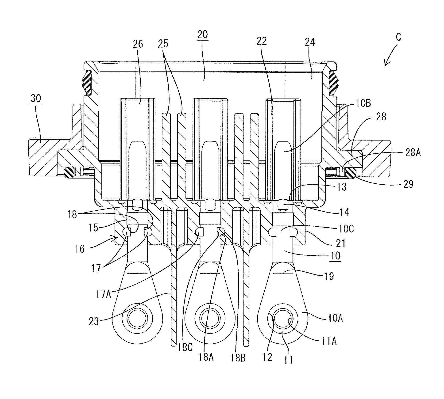
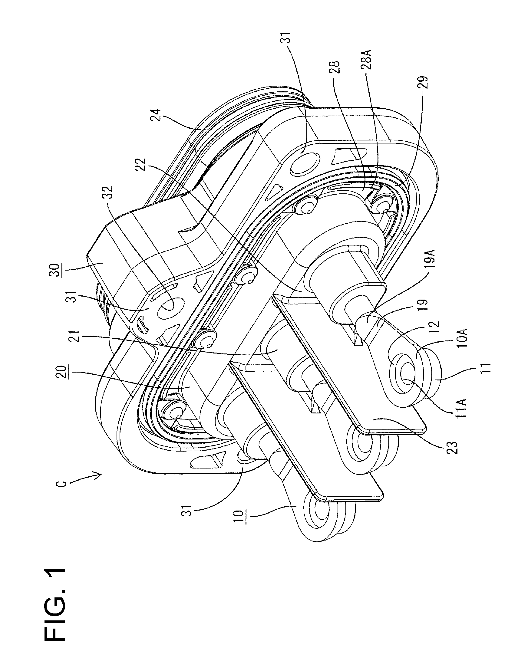
[0028]A connector C in this embodiment is a device connector used to supply power to an unillustrated load or device (e.g. motor mounted in an electric vehicle, a hybrid vehicle or the like). In the following description, an end (front of FIG. 1) to be connected with the device is referred to as the front, an opposite end is referred to as the rear, and upper and lower sides of FIG. 1 are referred to as the top and bottom for respective constituent members. Note that the device is to be housed in an unillustrated conductive metal case having a shield function and the connector C is to be mounted in a mounting hole in the case.

[0029]The connector C has terminal fittings 10 with embedded portions embedded in a housing 20 by insert molding so that a unitary matrix of synthetic resin surrounds and engages parts of the terminal fittings 10.

[0030]As shown in FIG. 1, the housing 20 has substantially cylindrical terminal holding portions 21 and substantially central portions of the terminal...


PUM


Abstract

A connector (C) is formed by insert molding such that terminal fittings (10) are embedded in a housing (20). A connecting portion (10A) provided at the front end of the terminal fitting (10) for connection to a mating terminal fitting projects forward from the housing (20) and a part of the terminal fitting (10) located behind the connecting portion (10A) is embedded in the housing (20). A seal (15) is provided in close contact with an embedded portion (10C) of the terminal fitting (10) embedded in the housing (20) and a resilient portion (19) is provided at a position before the seal (15) and outside the housing (20).

Description

BACKGROUND OF THE INVENTION[0001]1. Field of the Invention[0002]The invention relates to a connector.[0003]2. Description of the Related Art[0004]Known connectors are formed by insert molding so that part of a terminal fitting is embedded in a housing. More particularly, a connecting portion is provided at the front end of the terminal fitting and projects forward from the housing for connection to a mating terminal fitting and a part behind the connecting portion is embedded in the housing. A clearance may be formed in an adhering part of the terminal fitting and the housing of the insert molded connector due to low adhesion between two materials. Accordingly, water or oil may intrude into the housing through that clearance.[0005]U.S. Pat. No. 7,070,449 discloses adhering a seal to the outer peripheral surface of a part of a terminal fitting to be embedded in a housing and then performing insert-molding to ensure good waterproofing. However, waterproof performance may be reduced by...

Claims


Application Information

Patent Timeline
Patent Type & Authority Patents(United States)
IPC IPC(8): H01R13/40
CPCH01R13/521H01R43/24
Inventor MAEGAWA, AKIHITO
Owner SUMITOMO WIRING SYST LTD
Why Eureka
Try Eureka