Spring lock electrical fitting

a technology of electrical fittings and spring locks, applied in the field of spring locks, can solve the problems of requiring substantial effort to snap, affecting the safety of electrical fittings, and requiring substantial effort to complete all of these connections, and achieve the effect of reducing the amount of effort and force applied, and good grounding on both ends

Inactive Publication Date: 2014-07-29
KEEMEYA LLC DBA NEEKSON
View PDF25 Cites 19 Cited by
  • Summary
  • Abstract
  • Description
  • Claims
  • Application Information

AI Technical Summary

Benefits of technology

[0017]The tight engagement of the trailing prongs to the trough areas of the cable provides good surface contact between the trailing tangs and the cable, thus improving electrical continuity and grounding between the cable, the fitting, and the panel or junction box.
[0020]Therefore a secure and tool free method of installation or removal is made possible with minimal of effort and force applied, while maintaining a very good grounding on both ends of the connector.

Problems solved by technology

Therefore, it should be appreciated that completing all of these connections can be very time consuming, since contractors usually use such tools on each connection.
Although using such snap engagement fittings eliminates the use of tools for installation, they typically require substantial effort to snap them on the junction box or panel.
Furthermore, if there is a need for a retrofit or disconnection of the fitting, the contractors have no choice but to use tools to remove the snap engagement fittings and that, in turn, also involves substantial effort and force.

Method used


Image

  • Spring lock electrical fitting
  • Spring lock electrical fitting
  • Spring lock electrical fitting

Examples


Embodiment Construction

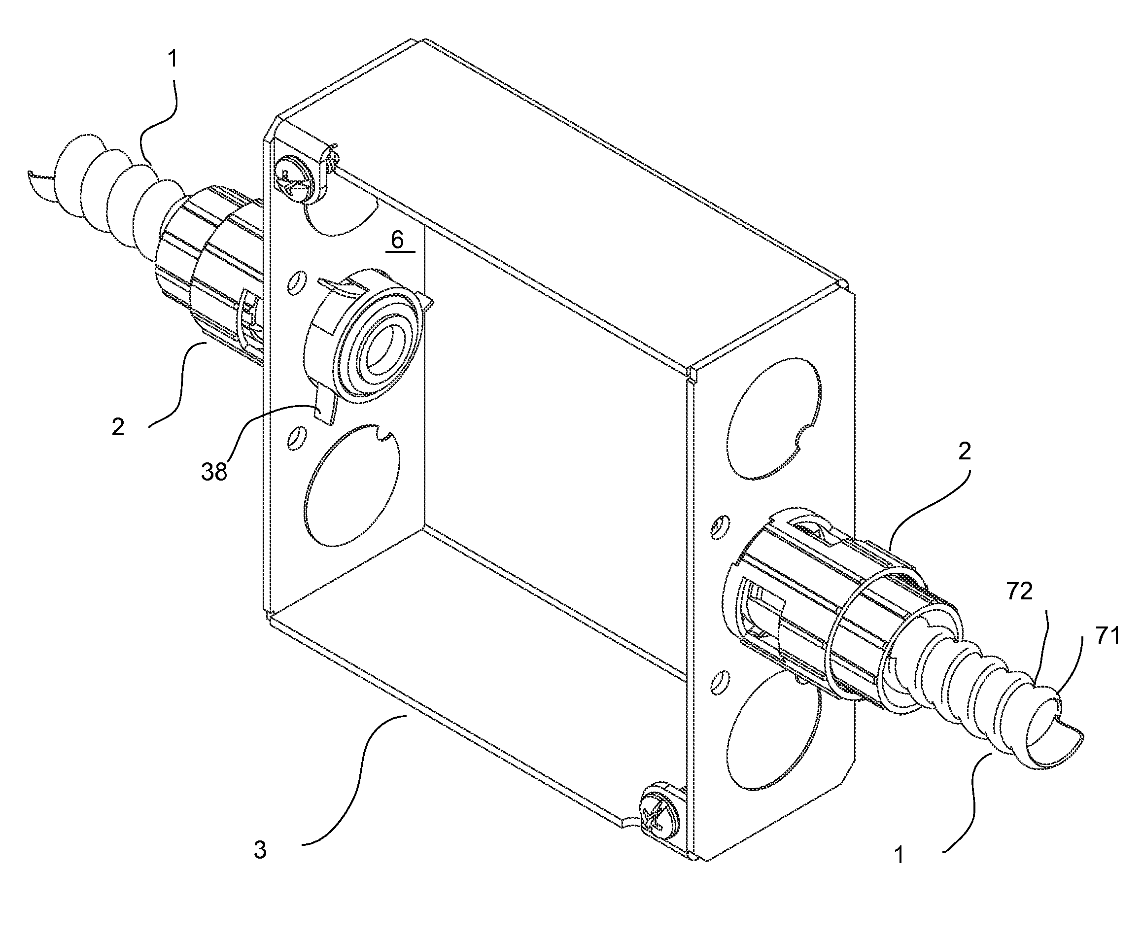
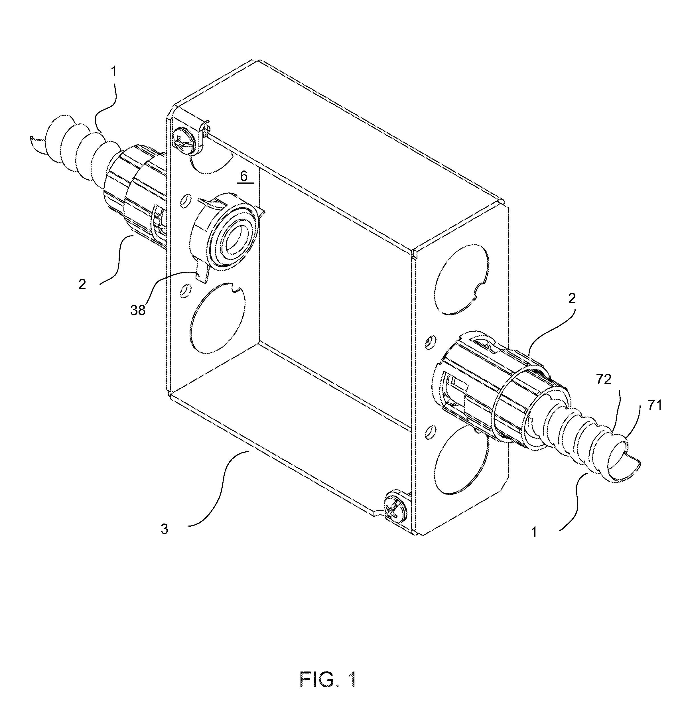
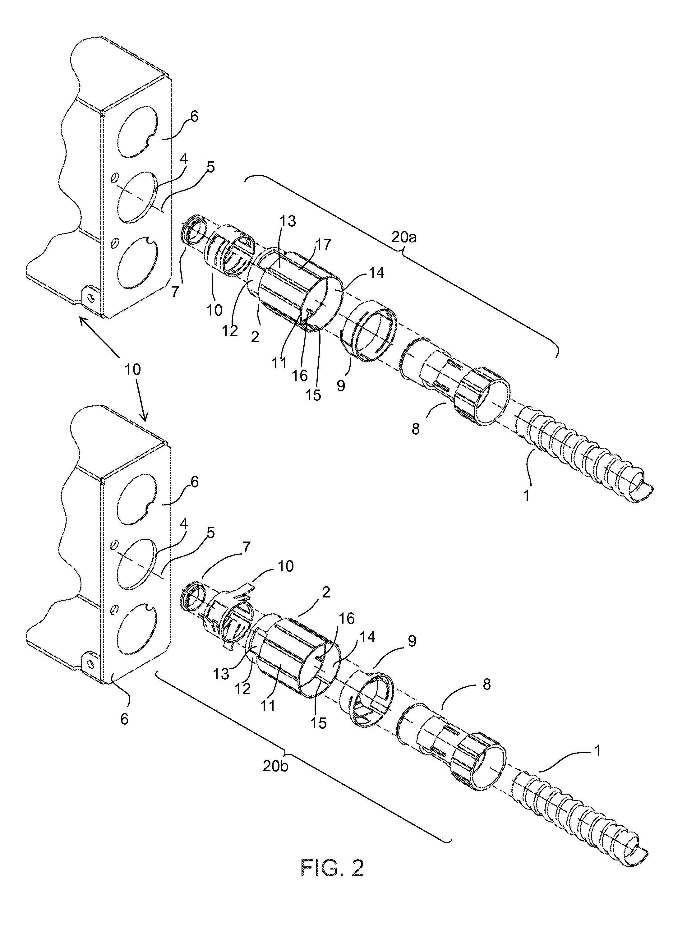
[0041]Turning first to FIGS. 1 and 2, the present invention provides an electrical fitting 2 that secures a flexible electrical cable conduit 1 to an electrical panel or junction box 3 through the knock out hole 4 shown in FIG. 1 and FIG. 2. In the present configuration, fitting 2 connects a flexible electrical conduit 1 which supports a plurality of electrical wires (not shown) to the electrical junction box 3 enabling a secure connection while it establishes a conductive path. Furthermore the fitting of the present invention enables spring lock engagement of the fitting 2 to the electrical junction box 3 on its leading end and spring lock engagement of the flexible electrical cable 1 to the fitting 2 on the trailing end of it. The flexible electrical cable conduit 1 generally consists of an outer metal sheath that has been formed from a strip of metal that has been helically wound and interlocked to produce a contour forming crowns 71 and troughs 72. (depicted in FIG. 14.)

[0042]FI...


PUM


Abstract

A fitting that anchors electrical wiring to a junction box or electrical panel includes gripping members which can releasably hold electrical wiring, in or out of armored conduit, and interference members which allow the fitting to be inserted through knock out apertures and, when in place, extend to prevent withdrawal from the aperture. Optionally a rotatable collar actuates the mechanisms and abuts the wall of the box or panel, eliminating any lateral movement when the interference members are engaged.

Description

[0001]This application claims the benefit of U.S. Provisional Patent Application No. 61 / 367,882, filed Jul. 27,2010 , the contents of which are incorporated in this disclosure by reference in their entirety.BACKGROUND OF THE INVENTION[0002]The present invention relates to fittings for connecting electrical cables and flexible conduit to electrical panels and junction boxes.[0003]The intention of the invention is to make an improved fitting that allows easier insertion of the electrical cables into the trailing end of the fitting and into the electrical panel or junction box at the same time. Historically, armored cable (AC) or metal-clad cable (MC) has been connected to a panel by a tubular fitting including a leading end having a threaded nose and a trailing end having a lateral screw mounted laterally through the fitting wall. Alternatively, a set of strap and screws were attached to the trailing end. The threaded nose was inserted into an aperture in the panel and a locknut tight...

Claims


Application Information

Patent Timeline
Patent Type & Authority Patents(United States)
IPC IPC(8): H02G3/18
CPCH02G3/0691
Inventor JAFARI, AFSHIN
Owner KEEMEYA LLC DBA NEEKSON
Why Eureka
Try Eureka