Motor vehicle with a device for supplying cooling air

a technology for motor vehicles and cooling air, which is applied in the direction of road transportation emission reduction, propulsion cooling, component optimization, etc., can solve the problems of severe change in lift balance and therefore driving performance, and achieve the effect of reducing lift and lifting

Active Publication Date: 2014-08-05
DR ING H C F PORSCHE AG
View PDF23 Cites 43 Cited by
  • Summary
  • Abstract
  • Description
  • Claims
  • Application Information

AI Technical Summary

Benefits of technology

[0008]The air-guiding device that is in the open position forms the upwardly curved, convex air-guiding surface that opens the downwardly U-shaped flow duct and can supply an upward air flow, for example, to cool the wheel brakes. The reaction force of the upward air flow reduces the front axle lift. The air-guiding device that is in the lowered closed position forms the level air-guiding surface and closes the flow duct. The front axle lift increases in this position and the aerodynamic drag is reduced, i.e. the front axle lift is higher and the aerodynamic drag is lower than in the open position with the convex air-guiding surface.
[0010]The radiator shutter permits control of an air mass flow through the radiator of the motor vehicle according to requirements and is used primarily for reducing the aerodynamic drag and fuel consumption. A reduction in the aerodynamic drag and fuel consumption is obtained by closing cooling air flaps. However, the position of the radiator cover can cause a front wheel lift force and therefore a pitching moment of the motor vehicle, which may lead to an overall severe change in the lift balance and therefore in the driving performance. Accordingly, the invention provides a first position where the cooling air flaps of the radiator shutter are completely open, and the flow duct of the air-guiding device is open and forms the upwardly convexly curved air-guiding surface.
[0013]In the second position, the cooling air flaps are closed and the air-guiding device also is closed and transferred into the level position, i.e. moved into what is referred to as the closed position. Accordingly, the reduction in the front axle lift, which is brought about by closing the cooling air flaps, is compensated for by the increase in the front axle lift produced by closing the flow duct. The aerodynamic drag is reduced further, since the advantage of the aerodynamic drag resulting from the closed radiator shutter and the reduction in the aerodynamic drag that is brought about when closing the flow duct add up in an aerodynamically advantageous manner. The reduction in the aerodynamic drag that is produced by the combination of the radiator shutter and the adjustable air-guiding device is therefore greater than the reduction brought about by the radiator shutter by itself.
[0016]The combination of closed cooling air flaps and the open air-guiding device with the convex air-guiding surface therefore is of advantage because the reduction in lift that arises when the radiator shutter is closed, and the reduction in lift that results with the open flow duct with the convex air-guiding surface, can add up in an advantageous manner in terms of driving dynamics.

Problems solved by technology

However, the position of the radiator cover can cause a front wheel lift force and therefore a pitching moment of the motor vehicle, which may lead to an overall severe change in the lift balance and therefore in the driving performance.

Method used


Image

  • Motor vehicle with a device for supplying cooling air
  • Motor vehicle with a device for supplying cooling air
  • Motor vehicle with a device for supplying cooling air

Examples


Embodiment Construction

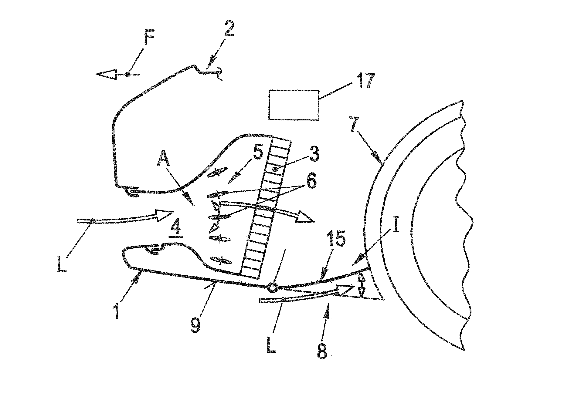
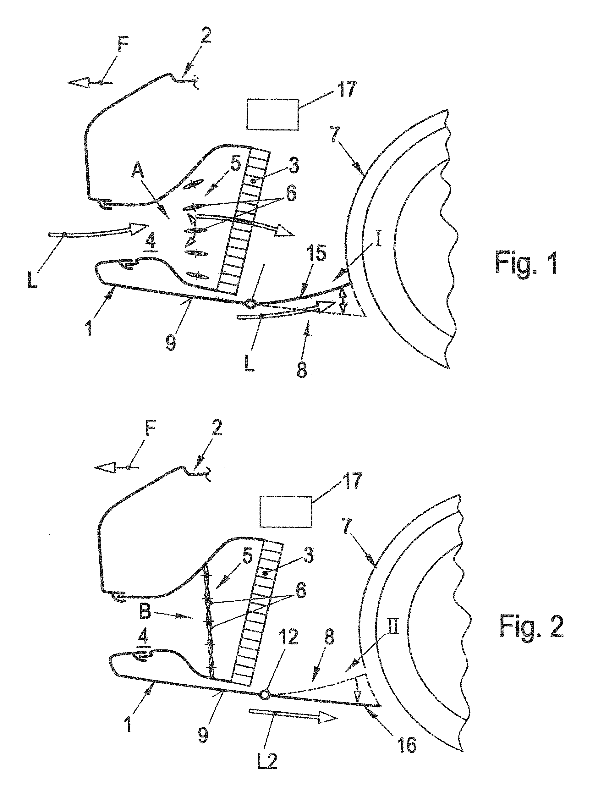
[0022]A cooling air controller and a driving controller in accordance with an embodiment of the invention are provided at a front end 1 of a vehicle 2 for supplying cooling air L to a radiator 3 via an air inlet duct 4. The cooling air controller and driving controller has a radiator shutter 5 with adjustable cooling air flaps 6 in front of the radiator. The vehicle 2 has a wheel house 7 downstream of the radiator 3 and an adjustable air-guiding device 8 is arranged between the radiator 3 and the wheel house 7 of the vehicle 2 on the lower side of the air inlet duct 4.

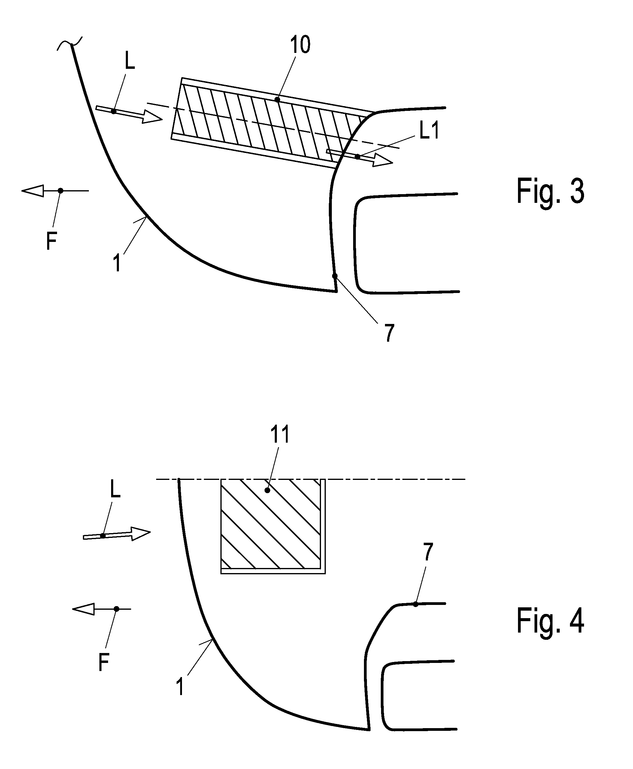
[0023]The air-guiding device 8 is arranged on the underbody 9 of the vehicle 2 and below a U-shaped, downwardly open flow duct 10 (FIG. 3) or an adjustable underbody diffuser 11 (FIG. 4) that can be positioned at an angle and is adjustable parallel to the underbody 9.

[0024]The air-guiding device 8 is adjustable about an axis 12 or another adjustable air-guiding element is mounted in the flow duct 10 for movement betwee...


PUM


Abstract

A motor vehicle has at least one adjustable air-guiding device on the underbody. The air-guiding device has a cross-sectionally U-shaped duct and is adjustable between a closed position and an open position. The motor vehicle also has a radiator device with a radiator and a radiator shutter with adjustable flaps for controlling the air flow through the radiator. A control device actuates the air-guiding device depending on the position of the radiator shutter so that, irrespective of the position of the flaps of the radiator shutter, an at least approximately identical pitching moment is obtained at the motor vehicle and at the same time the aerodynamic drag is reduced.

Description

CROSS REFERENCE TO RELATED APPLICATIONS[0001]This application claims priority under 35 USC 119 to German Patent Appl. No. 10 2012 102 445.6 filed on Mar. 22, 2012, the entire disclosure of which is incorporated herein by reference.BACKGROUND[0002]1. Field of the Invention[0003]The invention relates to a motor vehicle with a device for supplying cooling air.[0004]2. Description of the Related Art[0005]DE 10 2009 050 967 A1 discloses a closable air-conducting cooling system for a motor vehicle brake. The air-conducting cooling system is arranged on a front wheel guard and has at least one braking air duct in the bodywork at the front wheel guard. A closure device is arranged at the braking air duct and is movable between positions for opening or closing the braking air duct. The closure device has a housing arranged on an underbody at an end of the braking air duct that faces the front wheel guard and an extendable spoiler element is arranged in the housing.[0006]An object of the inve...

Claims


Application Information

Patent Timeline
Patent Type & Authority Patents(United States)
IPC IPC(8): B60K11/00
CPCB60K11/04B60K11/085Y02T10/88
Inventor WOLF, THOMAS
Owner DR ING H C F PORSCHE AG
Why Eureka
Try Eureka