Hinged closure for a container neck

a container neck and hinge technology, applied in the direction of closure lids, closure stoppers, liquid dispensing, etc., can solve the problems of significant limitations and the design of bayonet segments, and achieve the effect of reducing the selection of available materials, facilitating sterilization, and minimizing the danger of contamination

Active Publication Date: 2014-08-05
CREANOVA UNIVERSAL CLOSURES
View PDF46 Cites 22 Cited by
  • Summary
  • Abstract
  • Description
  • Claims
  • Application Information

AI Technical Summary

Benefits of technology

[0015]In an embodiment the second fastening means of the lid are of a bayonet-type. These bayonet-type second fastening means comprise first bayonet-segments protruding laterally inwardly suitable to interact in a closed position of the closure with corresponding second bayonet-segments arranged e.g. at a neck and protruding laterally outwardly. The first and the second bayonet segments are designed and arranged such that when the lid is moved with respect to the lower part on a path determined by the hinge the first and the second bayonet-segments mesh with each other in a first direction (direction of axis of rotation, respectively closure axis) when the lid is arranged above the neck. It is then possible to interlock the lid with respect to the neck by rotating at least the lid of the closure with respect to the neck by a certain angle around the closure axis (axis of rotation) such that the first and the second bayonet-segments securely mate with each other holding the closure in a closed position locked against relative axial movement. To avoid overturning of the closure stop elements may be foreseen, e.g. in that the bayonet-segments are designed such that they act as stop elements, and / or additional stop elements are arranged in the area between the lid and the neck. Such an arrangement may have the disadvantage that the bayonet-segments have a rather complicated design which might not be appropriate in certain fields of application. In an embodiment where the lid of the closure is at least in a closed position of the closure torsionally stiff interconnected to the base of the closure, alternatively or in addition stop elements preventing overturning of the closure may be foreseen in the area between the lower part of the closure (body) and the neck. This has the further advantage that the neck finish is more simple and in the mold design disadvantageous hindering undercuts can be avoided which results in a more simple mold design.
[0035]A closure according to the present invention is directed to an improved hinged closure molded in closed position, especially a hinged closure for pressurized beverages. The closure is provided with a latching mechanism offering the opportunity to lock the closure repeatedly even at high internal pressure. The closure may further comprise a tamper evidence means to prevent unforeseen and indicate initial opening.

Problems solved by technology

Direct connections by a single main hinge would be possible for certain applications although they are resulting in significant limitations e.g. with respect to the opening angle of the closure and its robustness.
Such an arrangement may have the disadvantage that the bayonet-segments have a rather complicated design which might not be appropriate in certain fields of application.

Method used


Image

  • Hinged closure for a container neck
  • Hinged closure for a container neck
  • Hinged closure for a container neck

Examples


Embodiment Construction

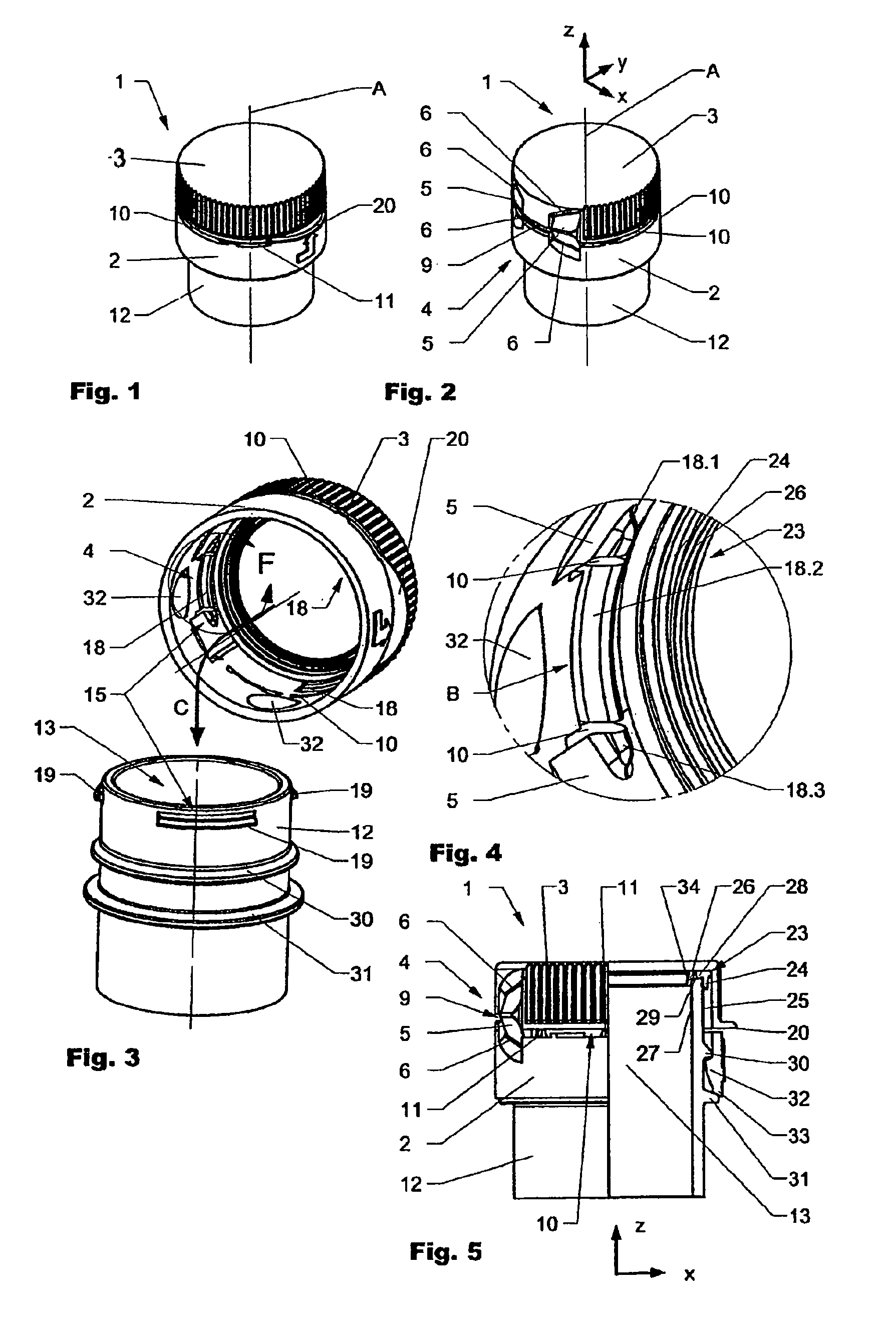
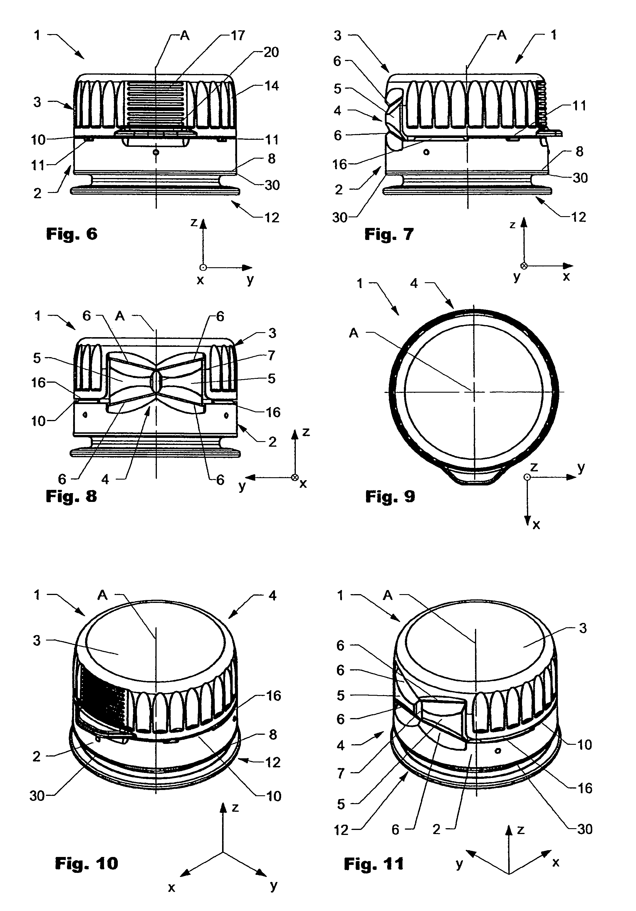
[0063]A better understanding of the present invention may be obtained by the present detailed description which, when examined in connection the accompanying drawings, sets forth embodiments of the inventions described herein. It should be understood that corresponding elements in the various figures are generally identified with corresponding reference numbers.

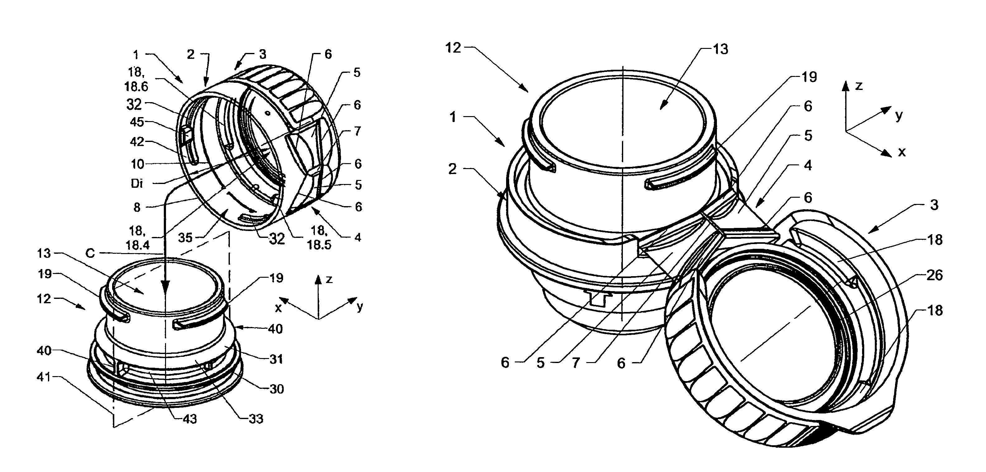
[0064]FIG. 1 is showing a hinged closure 1 according to the present invention in a perspective front view and FIG. 2 is showing the closure 1 in a perspective back view on a container neck 12.

[0065]The closure 1 comprises a ring-shaped lower part 2 (body) and a cap-like upper part 3 (lid) which are interconnected by a snap hinge 4. The hinge of the shown embodiment does not have a main hinge connection between the body 2 and the lid 3. The snap hinge 4 comprises a first and a second trapezoid element 5, of which each is connected to the body 2 and the lid 3 by the hinges. The hinge elements 6 are embodied as film hinges compr...


PUM

PropertyMeasurementUnit
opening angleaaaaaaaaaa
angleaaaaaaaaaa
angleaaaaaaaaaa

Abstract

The invention is directed to a hinged closure (1) preferably molded in a closed position. The closure has a base (2) and a lid (3) interconnected to the base by a hinge arrangement (4). A latching mechanism (15) holds the closure (1) in position with respect to a neck (12) and prevents unwanted opening.

Description

CROSS REFERENCE TO RELATED APPLICATIONS[0001]International Patent Reference PCT / EP2006 / 066429, filed 15 Sep. 2006, claims a foreign priority benefit under Title 35, United States Code, Section 119. International Patent Reference PCT / EP2006 / 066429 claims priority to U.S. Provisional Application, Ser. No. 60 / 717,466, filed on 15 Sep. 2005. International Patent Reference PCT / EP2006 / 066429 and U.S. Provisional Application Ser. No. 60 / 717,466 are hereby incorporated by reference herein in their entireties and are made a part hereof, including but not limited to those portions which specifically appear hereinafter.FIELD OF THE INVENTION[0002]The present invention is directed to a hinged closure suitable to be applied on a neck of a container and a neck of a container suitable to be used with the hinged closure according to the preamble of the independent claims.BACKGROUND OF THE INVENTION[0003]WO2005 / 007526 is directed to a hinged closure molded in a closed position which is suitable to b...

Claims


Application Information

Patent Timeline
Patent Type & Authority Patents(United States)
IPC IPC(8): B65D41/00
CPCY10T29/49821B65D50/061B65D47/0809B65D55/16B65D47/08B65D50/06
Inventor DRUITT, RODNEYLAGLER, LOUIS
Owner CREANOVA UNIVERSAL CLOSURES
Why Eureka
Try Eureka