
Integrated spring-activated ballistic insertion for drug infusion device

a technology of infusion device and ballistic insertion, which is applied in the field of infusion set, can solve the problems of affecting the performance of cumbersome and wasteful treatment methods, and inability to maintain an infusion site over an extended period of time, so as to reduce the overall size of the infusion set, avoid unwanted movement of the set, and avoid the effect of affecting the needle insertion and infusion performan

Active Publication Date: 2014-08-05
BECTON DICKINSON & CO
View PDF51 Cites 51 Cited by
  • Summary
  • Abstract
  • Description
  • Claims
  • Application Information

AI Technical Summary

Benefits of technology

The present invention provides an infusion set that can deliver insulin or other medicament to the upper layer of the skin surface, called the intradermal space, to improve drug absorption while still giving the user some comfort.

Problems solved by technology

The initial cost of the pump can be significant, but from a user perspective, the overwhelming majority of patients who have used pumps prefer to remain with pumps for the rest of their lives.
Accordingly, this method of treatment can become cumbersome and wasteful when dealing with the large number of required components.
Unfortunately, due to the relative thinness of the intradermal layer, inserting a needle at such depth and maintaining an infusion site over an extended period of time within this narrow band is difficult.
Further, most insulin infusion sets typically do not provide any features to isolate the inserted needle from shock or other external forces.
However, where an attempt is made to target the upper 3 mm of skin surface, any shock or movement of the set can adversely affect needle insertion and infusion performance.
However, during such removal, unwanted movement of the set can adversely affect needle insertion and infusion performance.
An additional problem encountered by users of such devices is skin surface “tenting” during needle insertion, where the skin surface is deflected somewhat prior to or during needle insertion which makes precisely targeting the upper 3 mm of skin surface difficult.

Method used


Image

  • Integrated spring-activated ballistic insertion for drug infusion device
  • Integrated spring-activated ballistic insertion for drug infusion device
  • Integrated spring-activated ballistic insertion for drug infusion device

Examples


first embodiment

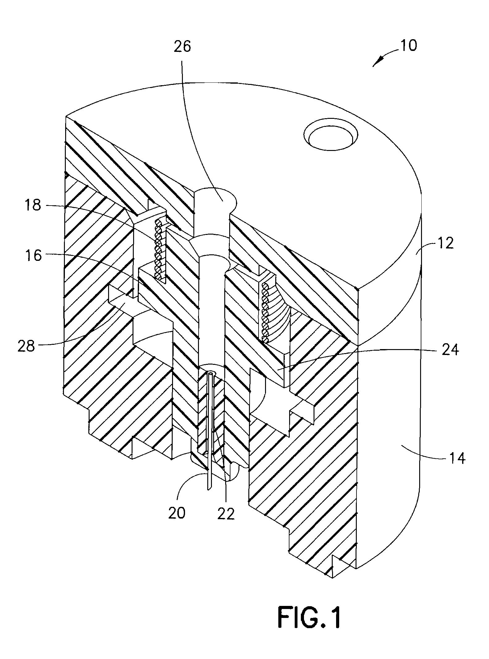
[0035]FIG. 1 is a perspective cross-sectional view of an integrated ballistic inserter in accordance with the present invention. As shown in FIG. 1, the exemplary integrated ballistic inserter 10 comprises a top 12, body 14, and a movable needle hub 16 captured therebetween. In exemplary embodiments of the present invention described below, the housings, hubs and other elements can be constructed of a molded plastic material, polycarbonate, thermoplastic polymer such as polyethylene terephthalate (PET and PETG), or similar materials. As shown in FIG. 1, the needle hub 16 comprises a needle or cannula 20 and hub 22. The needle 20 can preferably comprise a stainless steel or plastic needle / cannula, between 25 gauge and 36 gauge, provided with a single-bevel, tri-bevel or 5-bevel, and be between 1.0 and 10 mm long, but embodiments are not limited thereto. The needle 20 can be bonded to the hub 22 or other needle hub with an adhesive, such as a Loctite / UV cured adhesive, or can be over ...

second embodiment

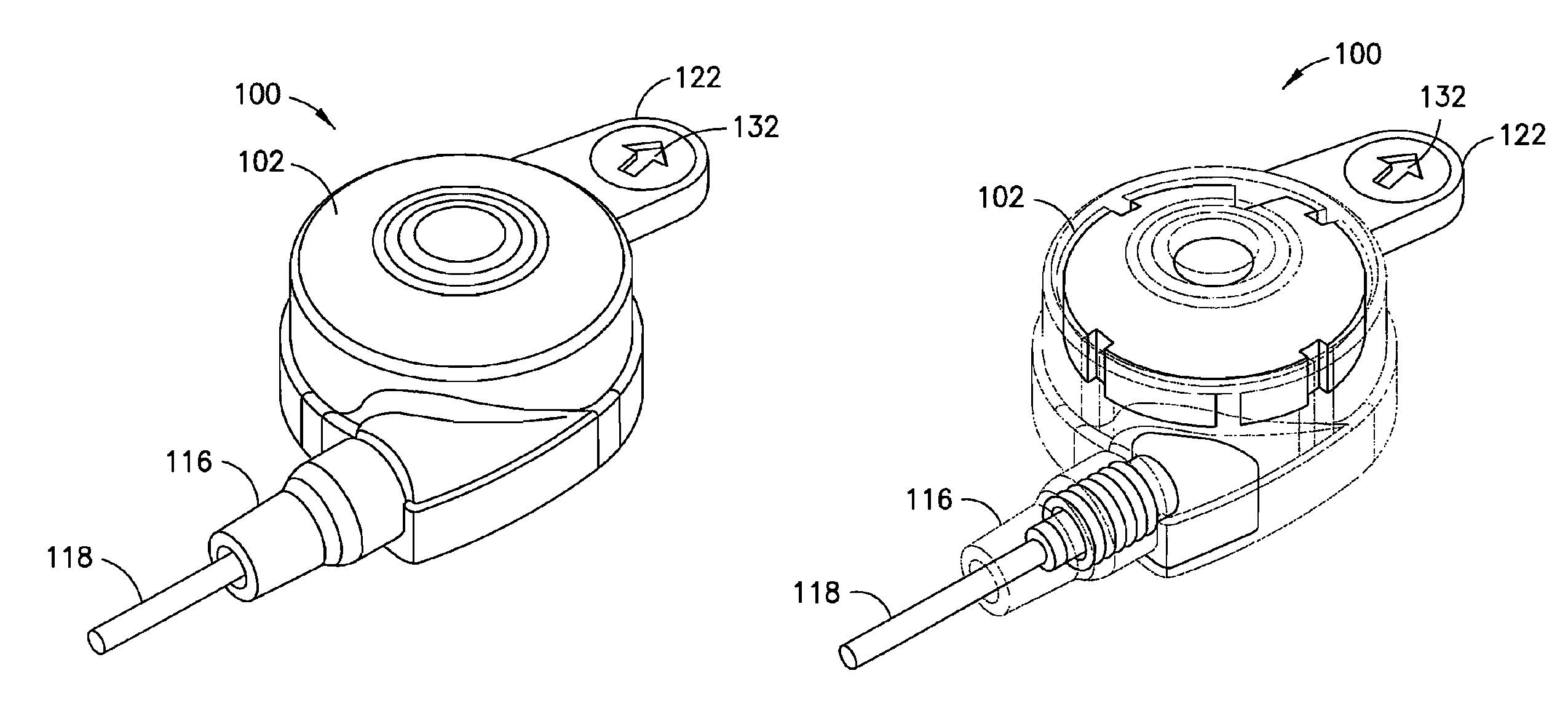
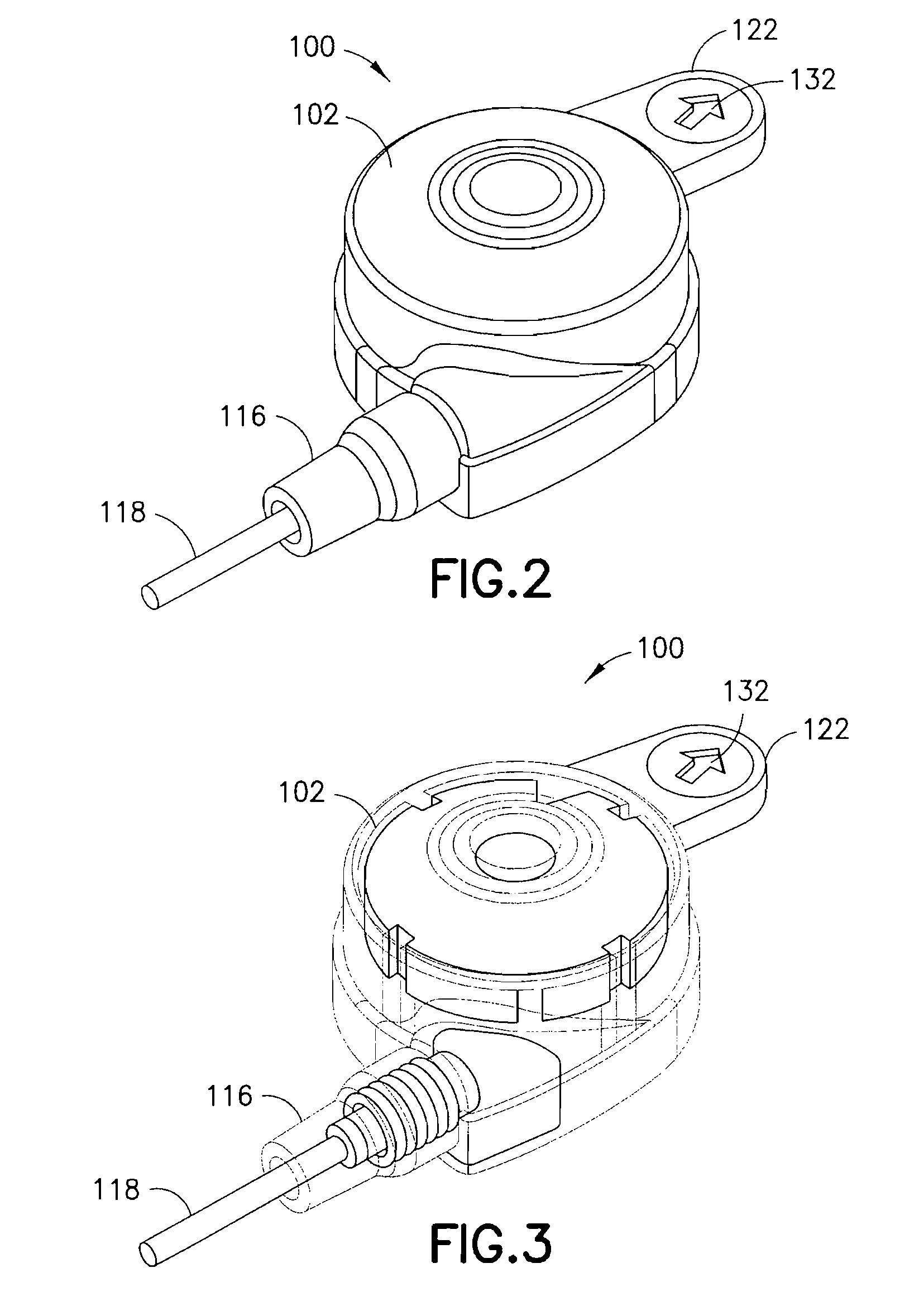
[0039]FIGS. 2-5 are views of an integrated ballistic inserter and infusion set 100 in accordance with the present invention. As shown in the exploded view of FIG. 4, the second exemplary embodiment of the present invention comprises a top 102, base ring 104 and bottom 106. Captured between the top 102 and bottom 106, a body 108, and needle 138 and needle hub 110, are provided. The needle hub 110 is provided with one or more O-rings 112 and 114 that are captured in grooves around an outer circumference of the needle hub 110 to allow the needle hub 110 to rotate freely and provide 360 degree rotation of the tubing attachment. The base ring 104 can be provided with an adhesive layer 134, and the bottom 106 can be provided with an adhesive layer 136, for securing each to a skin surface at the infusion site. The adhesive layers 134 and 136 are separate and can be provided with a single covering. The needle 138 can preferably comprise a stainless steel or plastic needle or cannula, betwee...

third embodiment

[0042]FIGS. 6-8 are views of an integrated ballistic inserter and infusion set 200 in accordance with the present invention. As shown in the exploded view of FIG. 6, the third exemplary embodiment of the present invention comprises a top 202 and bottom 204. Captured between the top 202 and bottom 204, a body 206 and needle 230 and needle hub 208 are provided. The bottom 204 can be provided with an adhesive layer 232 and covering for securing the bottom to a skin surface at the infusion site. The needle 230 can preferably comprise a stainless steel or plastic needle or cannula, between 25 gauge and 36 gauge, provided with a single-bevel, tri-bevel or 5-bevel, and be between 1.0 and 10 mm long, but embodiments are not limited thereto. The needle 230 can be bonded to the needle hub 208 with an adhesive, such as a Loctite / UV cured adhesive, or can be over molded with, or threaded into the hub.

[0043]As also shown in FIGS. 6 and 8, a drive spring 210 is captured between the top 202 of the...


PUM


Abstract

An infusion set has an integrated ballistic inserter that can insert a needle at a controlled high rate of speed to a depth to deliver content to the upper 3 mm of skin surface, and a skin securing, adhesive layer to secure the skin surface at the insertion site such that the inserter that can insert a needle without a risk of tenting of the skin surface. A driving spring of the ballistic inserter is captured within the ballistic inserter, and can be released by user operation, to insert a needle at such a controlled rate of speed.

Description

CROSS-REFERENCE TO RELATED APPLICATIONS[0001]This application claims the benefit under 35 U.S.C. §119(e) of a U.S. provisional patent application of Chris Kadamus et al. entitled “Integrated Spring-Activated Ballistic Insertion For Drug Infusion Device”, Ser. No. 61 / 344,967, filed on Nov. 30, 2010, the entire content of said application being incorporated herein by reference.FIELD OF THE INVENTION[0002]The present invention relates generally to infusion sets, including an integrated inserter for an infusion set, which ensures proper positioning of insertion by using an adhesive to hold an infusion set in position, and a ballistic inserter to first insert a needle at a controlled high rate of speed to a desired intradermal depth, and then hold the needle in an inserted position.BACKGROUND OF THE INVENTION[0003]A large number of people, including those suffering from conditions such as diabetes use some form of infusion therapy, such as daily insulin infusions to maintain close contro...

Claims


Application Information

Patent Timeline
Patent Type & Authority Patents(United States)
IPC IPC(8): A61M5/178
CPCA61M5/158A61M2005/1587A61M2005/1585A61M5/3287
Inventor KADAMUS, CHRISTOPHER J.IRWIN, STEPHEN J.ROUX, SERGEBENE, ERIC
Owner BECTON DICKINSON & CO
Learn More