Magnetic resonance imaging apparatus and magnetic resonance imaging method

a magnetic resonance imaging and magnetic resonance imaging technology, applied in the direction of diagnostic recording/measuring, using reradiation, instruments, etc., can solve the problems of insufficient fat suppression effect and more degraded images collected at later points in tim

Active Publication Date: 2014-08-05
TOSHIBA MEDICAL SYST CORP
View PDF9 Cites 8 Cited by
  • Summary
  • Abstract
  • Description
  • Claims
  • Application Information

AI Technical Summary

Benefits of technology

[0006]An MRI apparatus has a gradient magnetic field coil that applies a gradient magnetic field to an imaging space in which an object is placed, thereby providing an MR signal with spatial positional information. The gradient magnetic field coil generates significant heat during imaging because of a pulse current repeatedly supplied thereto. As the temperature of the gradient magnetic field coil rises, the temperature of an iron shim nearby also rises, and the magnetic permeability of the iron shim varies. As a result, the magnetic field in the imaging space varies, and the center frequency of the magnetic resonance of hydrogen atoms in the object also varies.

Problems solved by technology

However, if the center frequency of the magnetic resonance of the hydrogen atoms in a fat tissue shifts because of the heat generation of the gradient magnetic field coil during imaging after the conditions concerning the fat suppression prepulse is set in the imaging preparation step, the effect of the fat suppression can be inadequate.
If this occurs, images collected at later points in time may be more degraded because of the degradation of the effect of the fat suppression prepulse.

Method used


Image

  • Magnetic resonance imaging apparatus and magnetic resonance imaging method
  • Magnetic resonance imaging apparatus and magnetic resonance imaging method
  • Magnetic resonance imaging apparatus and magnetic resonance imaging method

Examples


Embodiment Construction

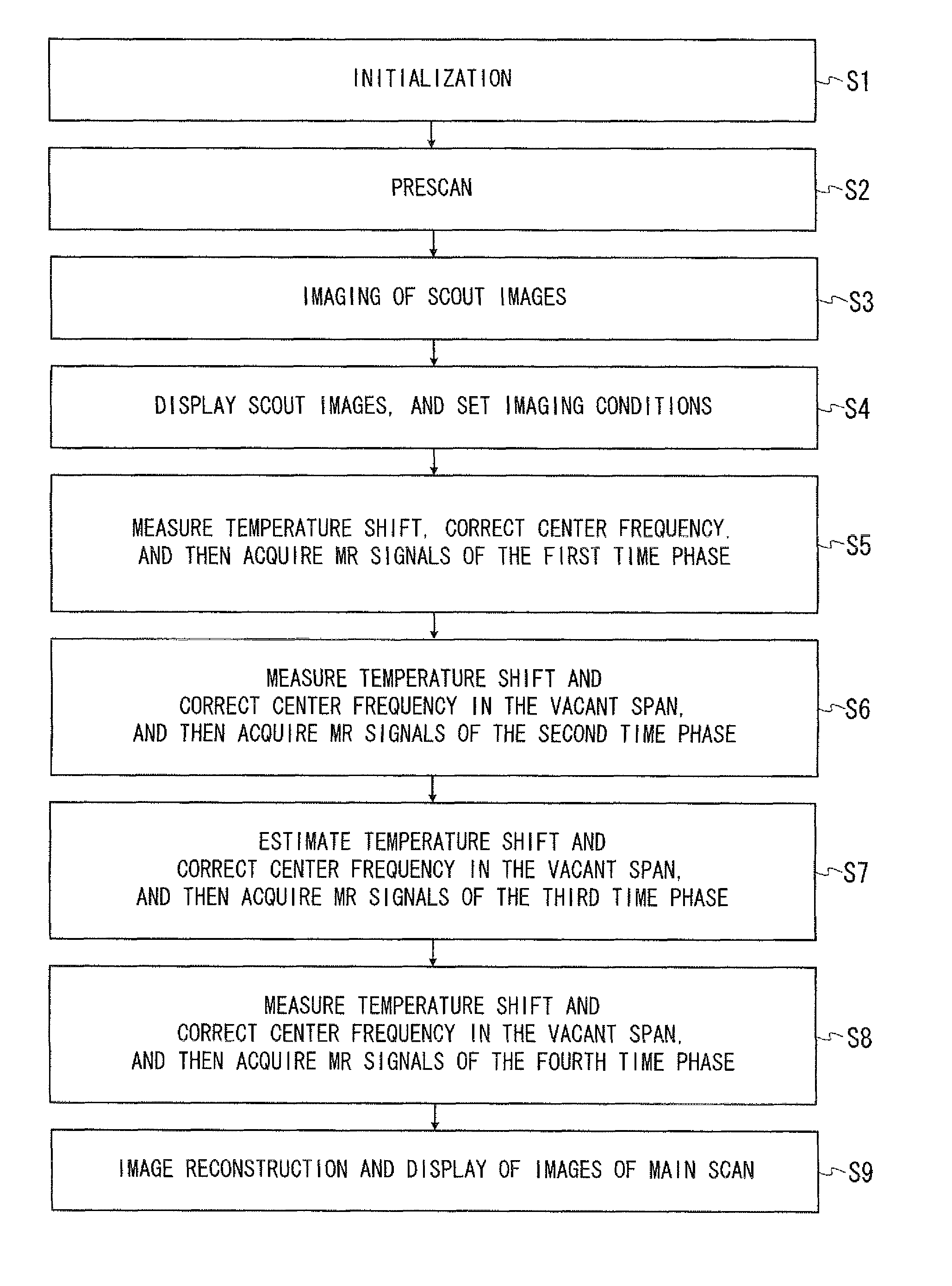
[0021]An embodiment of the present invention aims to provide an MRI technology which produces a high-quality image even if a center frequency of magnetic resonance of hydrogen atoms shifts because of heat generation of a gradient magnetic field coil, in a manner different from the conventional techniques. However, the present invention is not limited to this aim.

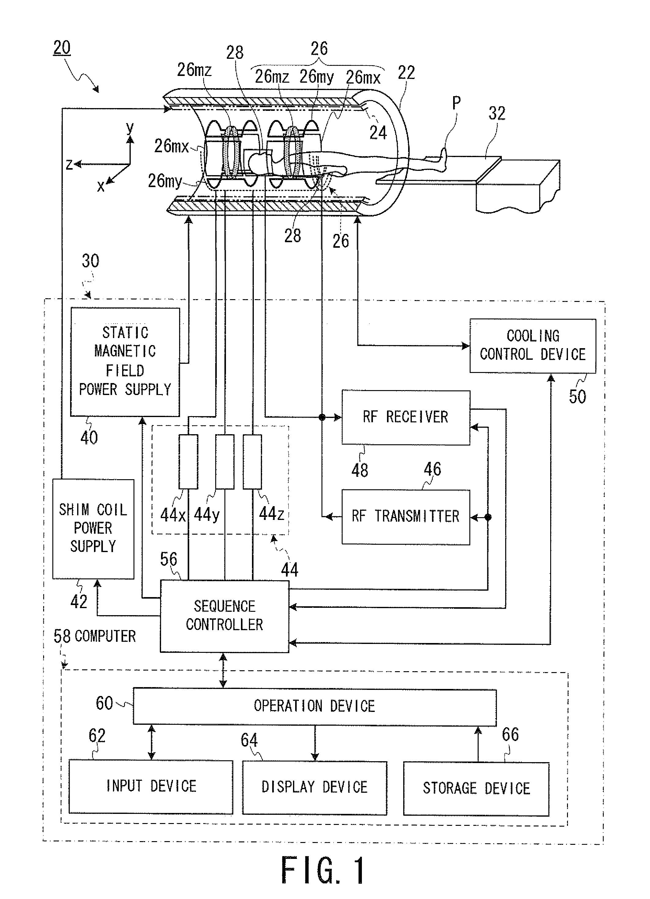
[0022]According to one embodiment, an MRI apparatus includes a gradient magnetic field coil unit, a temperature measuring unit, a data storing unit, a pulse setting unit and an imaging unit.

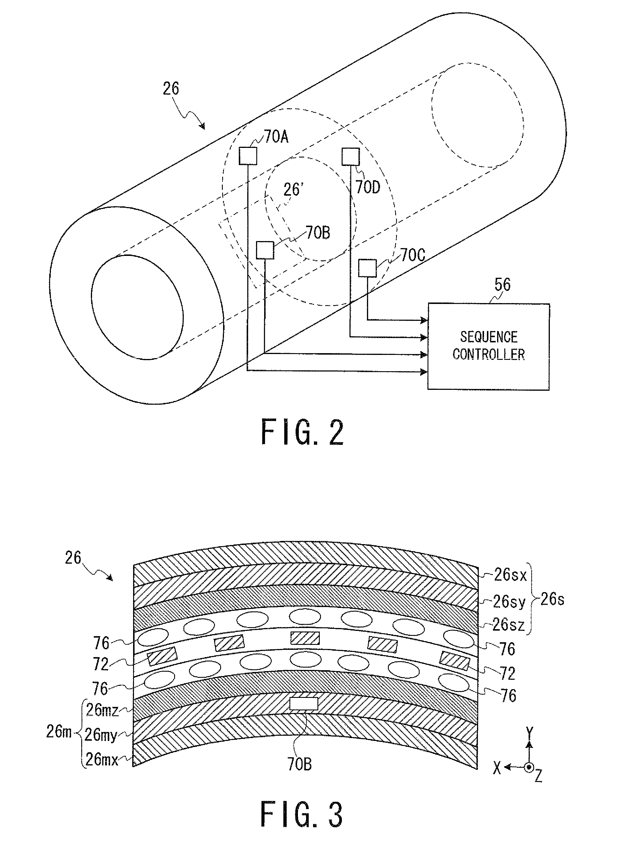
[0023]The gradient magnetic field coil unit generates a gradient magnetic field in an imaging space according to a current supplied thereto.

[0024]The temperature measuring unit measures a temperature of the gradient magnetic field coil unit at least two times at different timings.

[0025]The data storing unit stores shift data in advance of measurement by the temperature measuring unit. The shift data indicates a shift of a center frequency...


PUM


Abstract

The temperature of an MRI gradient magnetic field coil unit is measured at least two times. Shift data indicating a center magnetic resonance frequency of a hydrogen atom in response to variation of the gradient coil temperature is stored in advance. Estimated shift of the center frequency based on the measurement result is determined and the center frequency of an RF NMR excitation pulse is corrected based on the estimated shift.

Description

CROSS-REFERENCE TO RELATED APPLICATION(S)[0001]This application is based upon and claims the benefit of priority from Japanese Patent Application No. 2010-152213, filed on Jul. 2, 2010, and Japanese Patent Application No. 2011-131069 filed on Jun. 13, 2011; the entire contents of which are incorporated herein by reference.BACKGROUND OF THE INVENTION[0002]1. Field of the Invention[0003]Embodiments described herein relate generally to a magnetic resonance imaging apparatus and a magnetic resonance imaging method.[0004]2. Description of the Related Art[0005]MRI is an imaging method which magnetically excites nuclear spin of an object (a patient) set in a static magnetic field with an RF pulse having the Larmor frequency and reconstructs an image based on MR signals generated due to the excitation. The aforementioned MRI means magnetic resonance imaging, the RF pulse means a radio frequency pulse, and the MR signal means a nuclear magnetic resonance signal.[0006]An MRI apparatus has a g...

Claims


Application Information

Patent Timeline
Patent Type & Authority Patents(United States)
IPC IPC(8): G01V3/00
CPCA61B5/055A61B5/4869G01R33/5607G01R33/56308G01R33/56563
Inventor OOKAWA, MASASHI
Owner TOSHIBA MEDICAL SYST CORP
Why Eureka
Try Eureka