Method and device for arc spraying

a technology of arc spraying and spraying materials, applied in plasma techniques, lighting and heating apparatus, domestic stoves or ranges, etc., can solve problems such as layer defects, achieve the effects of improving the spraying behaviour of one or a plurality of spray filler materials, saving energy, and increasing the melting ra

Inactive Publication Date: 2013-01-10
LINDE AG
View PDF20 Cites 8 Cited by
  • Summary
  • Abstract
  • Description
  • Claims
  • Application Information

AI Technical Summary

Benefits of technology

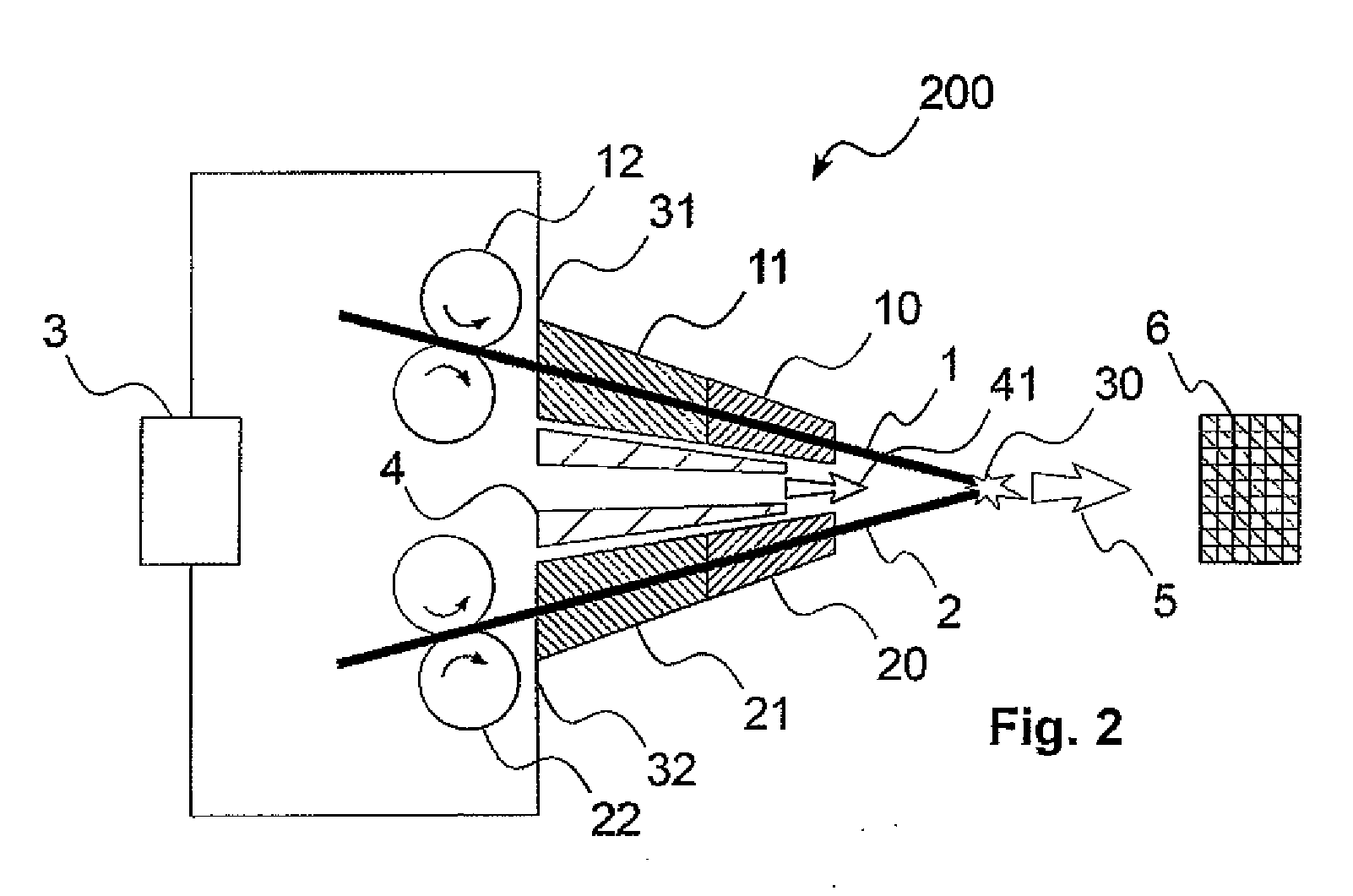
[0011]According to the invention, a fusing behaviour of one or a plurality of spray filler materials is improved during arc spraying in that at least one of the wire-shaped spray filler materials is preheated before the melting in the arc. As it was possible to discover according to the invention, an increased melting rate is achieved by means of this preheating of the filler material.
[0012]A fusing process can be stabilised by means of a preheated spray filler material, which has reproducible results during arc spraying as a consequence. A spray filler material melted by means of an arc can be atomised better and an increase of the particle speed can be effected for example on account of changed viscosity properties. The advantages achieved according to the invention furthermore contain a significant saving of energy and a processing of higher melting materials (spray filler materials) is enabled, as a relatively large heat quantity (namely that of the preheating in addition to that of the arc) can be introduced by means of the preheating. In particular, the formation of spatters can be reduced. Spatters here means relatively large portions of detached wire material, which are created by short circuits and which are then also sprayed in an uncontrolled manner, that is to say with non-settable speed, temperature and size, and then cause layer defects. Furthermore, the fusing process can be stabilised as a whole by means of the preheating. More than in the case of a known heating of an atomising gas flow, a heating can take place on a wire-by-wire basis. This is particularly advantageous in the case of two-wire systems.
[0013]With particular advantage, in the context of the method according to the invention, at least one wire-shaped spray filler material is preheated to a temperature which lies between room temperature and a solidus temperature of the spray filler material. As a result, the maximum heat can be introduced into a corresponding spray filler material and at the same time a handling of a corresponding wire-shaped material in a spray device (for example by means of a feed apparatus) can be ensured. With particular advantage, in the context of the method according to the invention, the atomising gas flow is preheated to a temperature which lies between room temperature and 1000° C. In particular, the maximum heat can be introduced.
[0014]Further advantages can be achieved if the atomising gas flow is additionally preheated. As a result, as already mentioned at the beginning, its speed can be increased and / or the total energy quantity in the system can be increased further. The increased speed is in particular very advantageous if an influencing, in particular an influencing on a wire-by-wire basis, of the corresponding material properties has been carried out. A heating of wire and atomising gas flow may thus provide an above-average value added. It can likewise take place by means of the below mentioned heating apparatuses.

Problems solved by technology

Spatters here means relatively large portions of detached wire material, which are created by short circuits and which are then also sprayed in an uncontrolled manner, that is to say with non-settable speed, temperature and size, and then cause layer defects.

Method used


Image

  • Method and device for arc spraying
  • Method and device for arc spraying
  • Method and device for arc spraying

Examples


Embodiment Construction

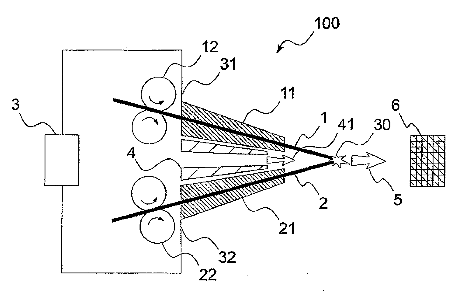
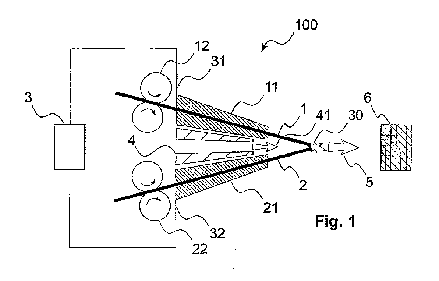
[0029]A device 100 for arc spraying according to the prior art is schematically illustrated in FIG. 1.

[0030]In the device 100, a first 1 and a second 2 wire-shaped spray filler material are guided towards one another by means of a wire guide 11, 21 in each case. To feed the wire-shaped spray filler materials 1, 2 towards one another, feed apparatuses 12, 22 are provided in the form of rollers or rolls rotating in the direction of the arrow.

[0031]Further, a current source 3 is provided, which is connected to the wire guides 11, 21 via electrical connections 31, 32 for loading the wire-shaped spray filler materials 1, 2. In a region in which the wire-shaped spray filler materials have a sufficiently small spacing, an arc 30 forms, by means of which the material of the wire-shaped spray filler materials 1, 2 is melted. An atomising gas nozzle 4 is provided, by means of which an atomising gas flow 41 is provided and guided. The atomising gas flow 41 effects an atomisation of the wire fi...


PUM

PropertyMeasurementUnit
temperatureaaaaaaaaaa
voltageaaaaaaaaaa
speedaaaaaaaaaa

Abstract

A method for arc spraying in which at least one wire-shaped spray filler material is melted in an arc by means of electric current and atomised by means of an atomising gas flow and applied in the form of a particle stream onto a workpiece, at least one wire-shaped spray filler material being preheated before the melting in the arc.

Description

CROSS REFERENCE TO RELATED APPLICATIONS[0001]This application claims priority from German Patent Application 102010064133.2 filed Dec. 23, 2010 and European Patent Application 11003382.6 filed Apr. 21, 2011.BACKGROUND OF THE INVENTION[0002]The present invention relates to a method for arc spraying, in which at least one wire-shaped spray filler material is melted in an arc by means of electric current and atomised by means of an atomising gas flow and applied in the form of a particle stream onto a workpiece, as well as a corresponding device.[0003]Arc spraying is a thermal spraying method in which a wire-shaped spray filler material is melted by means of an electric current, using which an arc is created. A corresponding device is described e.g. in U.S. Pat. No. 2,982,845 A.[0004]To this end, conventionally two electrically conductive metallic wires are used, which are continuously fused as electrodes, so-called one wire methods are likewise known however. A voltage of usually 15 t...

Claims


Application Information

Patent Timeline
Patent Type & Authority Applications(United States)
IPC IPC(8): C23C4/12B05B7/16
CPCC23C4/125B05B7/224C23C4/131
Inventor SCHEIN, JOCHENHEINRICH, PETERKROMMER, WERNER
Owner LINDE AG
Why Eureka
Try Eureka