Thermosyphon heat reduction system for a motor vehicle engine compartment

a technology of heat reduction system and engine compartment, which is applied in the direction of machines/engines, combustion air/fuel air treatment, lighting and heating apparatus, etc., can solve the problems of difficult movement of air through the engine compartment that can help to some extent in limiting the underhood temperature, and the effect of affecting the performance and durability of various devices and systems

Inactive Publication Date: 2010-01-05
INT TRUCK INTPROP LLC
View PDF18 Cites 9 Cited by
  • Summary
  • Abstract
  • Description
  • Claims
  • Application Information

AI Technical Summary

Benefits of technology

[0007]The present invention relates to a system for removing significant engine heat from an engine compartment in a motor vehicle, especially heat generated by operation of a heat engine in an engine compartment. By using the thermosyphon principle, the inventive system enables heat to be removed by natural circulation of thermofluid thereby rendering the system passive in the sense that it does not draw power from either the engine or the electrical system. The amount of heat that can be removed can be large enough to provide a significant limitation on excessive underhood temperatures.

Problems solved by technology

Underhood temperature is a matter of concern to vehicle designers because excessively high temperatures can have adverse effects on the performance and durability of various devices and systems.
Space within an engine compartment is often at a premium, and the more crowded an engine compartment becomes, more components are exposed to engine compartment heat, and the movement of air through the engine compartment that can aid to some extent in limiting underhood temperatures becomes more difficult.
Moreover, placement of a radiator in certain vehicles causes at least some of the engine heat that is rejected at the radiator to pass through the engine compartment.

Method used


Image

  • Thermosyphon heat reduction system for a motor vehicle engine compartment
  • Thermosyphon heat reduction system for a motor vehicle engine compartment
  • Thermosyphon heat reduction system for a motor vehicle engine compartment

Examples


Embodiment Construction

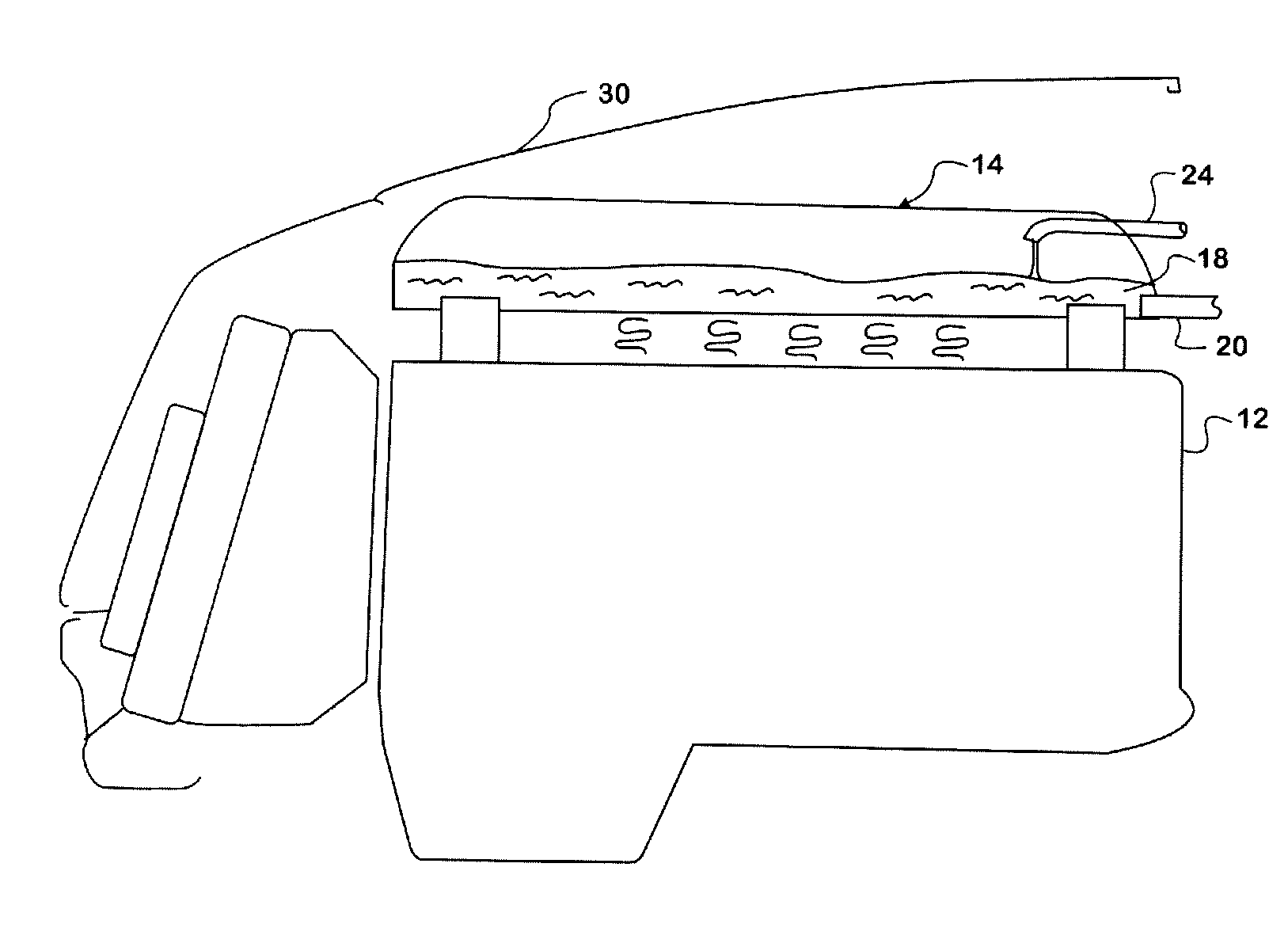
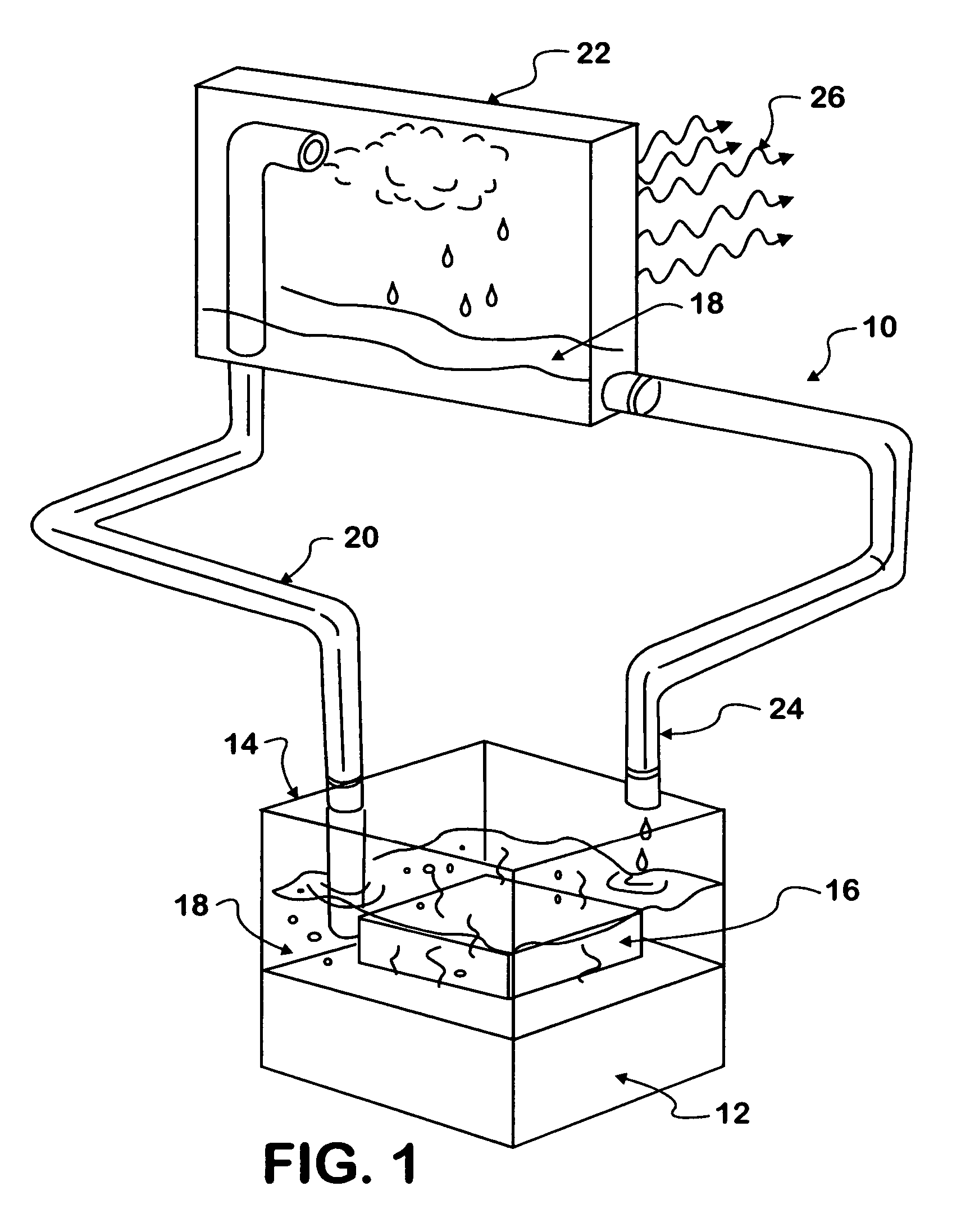
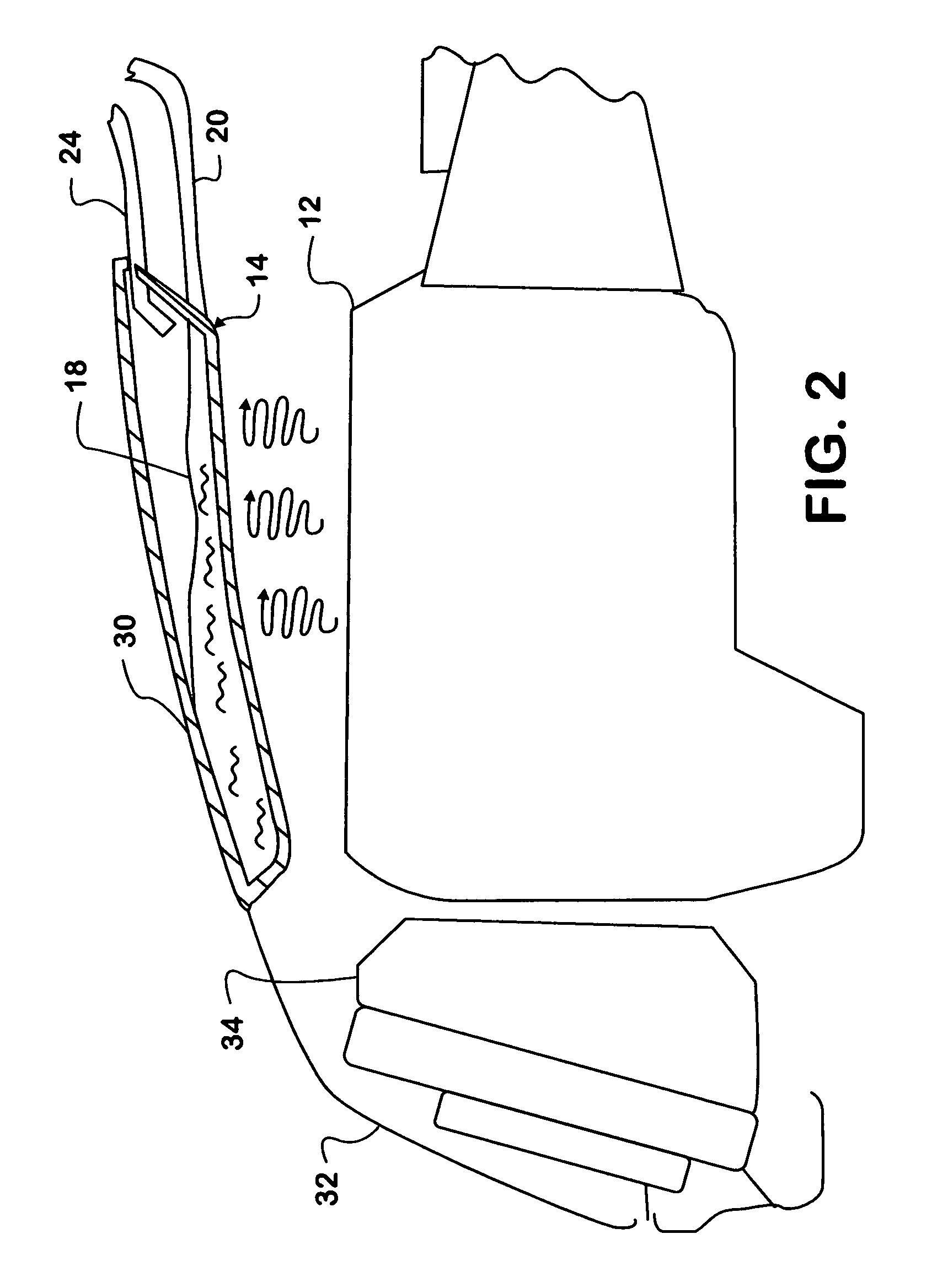
[0016]FIG. 1 shows a schematic representation of a thermosyphon system 10 associated a heat engine 12 in a motor vehicle, such as a truck. Engine 12 is mounted on a chassis frame and forms the powerplant that propels the vehicle.

[0017]System 10 comprises a reservoir 14 and a heat collector 16. The latter is disposed to collect heat from engine 12 via conduction and / or convention, and / or radiation. Removal of heat by conduction occurs when collector 16 is placed in physical contact with engine 12. Removal of heat by convection occurs when air that has been heated passes across a surface of collector 16. Removal of heat by radiation occurs when collector 16 is radiantly heated by engine 12. Collector 16 transfers collected heat to thermofluid 18 in reservoir 14.

[0018]By making collector 16 a “black body” as that term is understood in physics, it becomes an ideal absorber of radiant heat. Hence, a surface of collector 16 is exposed to the radiant heat source, and it is through that sur...


PUM


Abstract

A system (10) and method for removing heat from an engine compartment in a motor vehicle where heat generated by operation of a heat engine (12) that propels the vehicle tends to collect. Engine heat is collected in a thermofluid in a reservoir forming an evaporator (14) where the thermofluid absorbs heat sufficient to evaporate it. The vapor naturally migrates to a condenser (22) that is cooled sufficiently to condense the vapor back to liquid phase. The liquid falls by gravity back to the condenser.

Description

FIELD OF THE INVENTION[0001]This invention relates to motor vehicles that are powered by heat engines and more particularly to a system for removing heat from any location in a vehicle that is prone to undesirably high temperatures, especially heat generated by a heat engine in an engine compartment.BACKGROUND OF THE INVENTION[0002]The nature of the thermodynamic cycle on which a heat engine operates requires that heat of combustion be rejected to a waste heat medium. In an air-cooled engine, the medium is air that surrounds the engine. In a liquid-cooled engine, the medium is liquid that circulates through coolant passages in the engine where it is heated before passing to a radiator where the heat is transferred to air that flows through the radiator, although some amount of heat is also rejected directly to air surrounding the engine by radiation and convection.[0003]A motor vehicle typically houses the engine in some sort of a compartment. Most cars and trucks have a front engin...

Claims


Application Information

Patent Timeline
Patent Type & Authority Patents(United States)
IPC IPC(8): B60H1/00F01N5/02F24H9/02
CPCF01P3/22F01P2003/2228F01P2003/225
Inventor BRADLEY, JAMES C.MARSHALL, CHRISTINAKLINGER, RODNEY J.WOOLDRIDGE, SCOTT A.PENALOZA, JOSEPH T.
Owner INT TRUCK INTPROP LLC
Why Eureka
Try Eureka