Thermally-armored radio-frequency identification device and method of producing same

a radio-frequency identification and thermal armored technology, applied in the field of radio-frequency identification (rfid) technology, can solve the problems of restricting the use of the rfid tag, largely undetected, and subject to removal or tampering

Inactive Publication Date: 2014-01-16
AITA
View PDF4 Cites 8 Cited by
  • Summary
  • Abstract
  • Description
  • Claims
  • Application Information

AI Technical Summary

Benefits of technology

[0023]The outer protective thermal armor may be any thermally-protective coating, n

Problems solved by technology

The armoring, however, is primarily for physical protection of the RFID tag rather than thermal protection and the large size of the armored RFID tag restricts its uses.
Further, these passive RFID devices may be concealed within or on the surface of products or their external packaging, thereby leaving them largely un

Method used


Image

  • Thermally-armored radio-frequency identification device and method of producing same
  • Thermally-armored radio-frequency identification device and method of producing same

Examples


Embodiment Construction

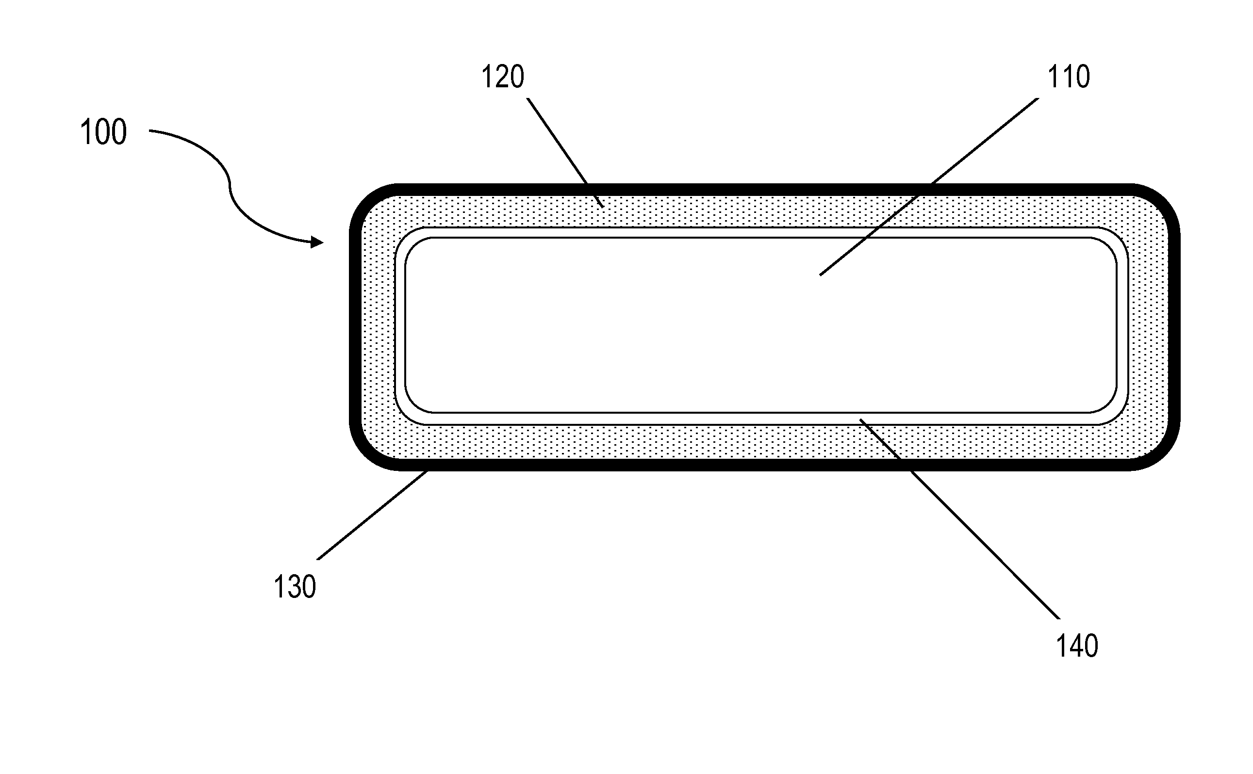
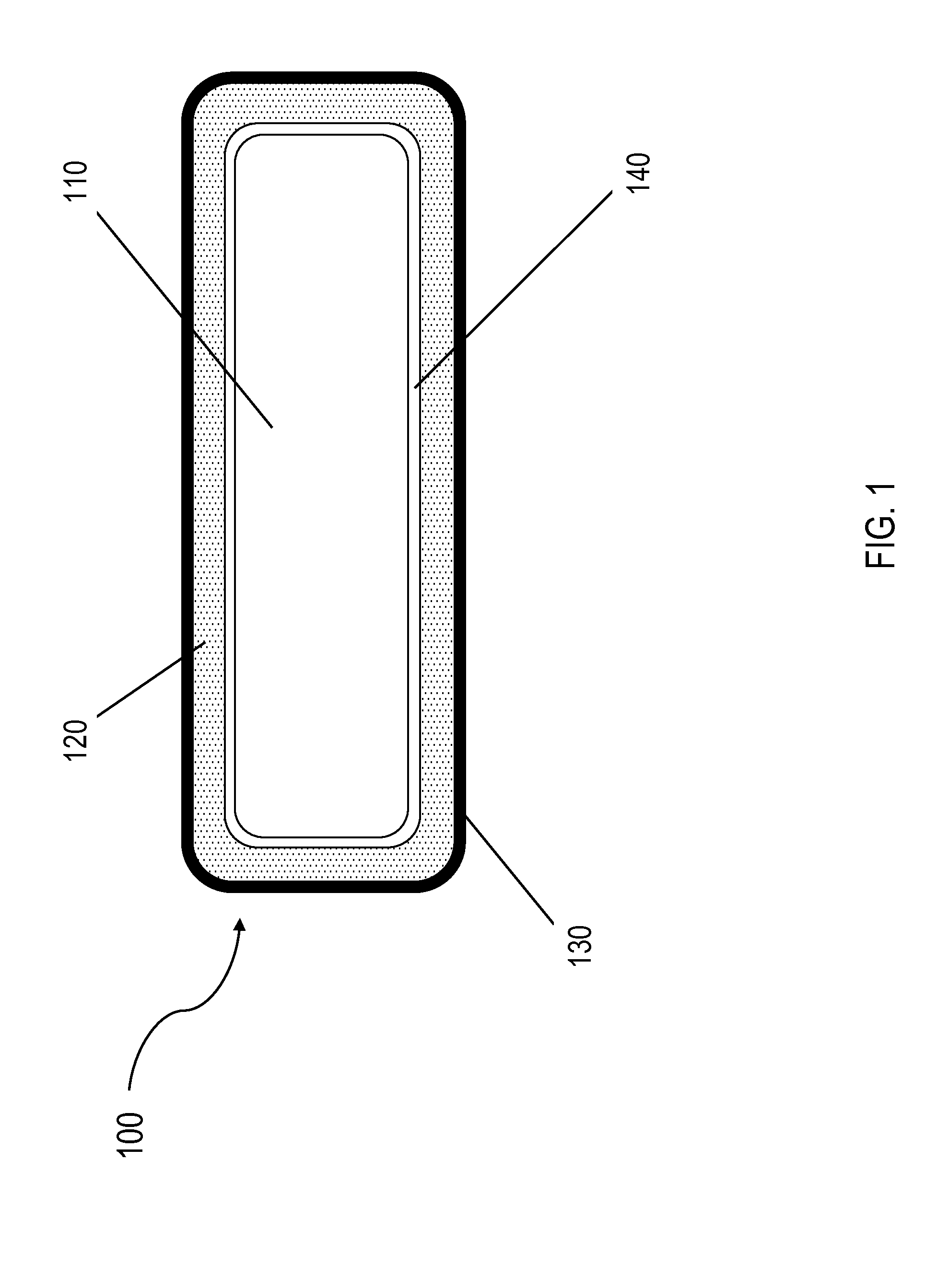
[0026]In one embodiment, a method comprises inserting an RFID tag, which may be either passive, battery-assisted passive, or active, within the material of an item or product, thereby concealing it permanently within such item or product and greatly increasing the ability to conceal it from detection or efforts at tampering with or deactivating it.

[0027]In one embodiment, the thermally-armored RFID tag is designed to withstand enormous heat conditions and certain high-heat conditions found in the molding of plastics, the fabrication of metal products, and any other product fabrication processes involving temperatures that would normally make RFID tag insertion impossible without destruction of the device due to ambient heat. Such insertion of currently-available RFID tags during the high-heat stages of certain product fabrication is not impossible using the method and materials of the invention. In one embodiment, the thermally-armored RFID tag is an improvement over some of the abo...


PUM

PropertyMeasurementUnit
Temperatureaaaaaaaaaa

Abstract

A thermally-armored RFID tag is configured to withstand extreme temperatures associated with certain product fabrication, including, but not limited to, the temperatures of molten metal and plastic. The thermal protection allows the RFID tag to be inserted into products during their fabrication, molding, casting, or extrusion, instead of being applied to the surface or inserted into the surface of the products after their fabrication

Description

REFERENCE TO RELATED APPLICATIONS[0001]This application claims the benefit of U.S. Provisional Patent Application Number 61 / 454,159, filed Mar. 18, 2011 and titled Thermally-Armored Radio-Frequency Identification Device and Method of Producing Same, the contents of which are incorporated herein by reference in their entirety.BACKGROUND OF THE INVENTION[0002]1. Field of the Invention[0003]The invention pertains to the field of radio-frequency identification (RFID) technology. More particularly, the invention pertains to methods and devices for thermally-resistant RFID devices and methods of making same.[0004]2. Description of Related Art[0005]An RFID system conventionally includes two fundamental parts, namely a “reader” (also known as an “interrogator”) or radio signal receiver and a transmitting “tag” or RFID tag. Radio wave communication data exchange between the tag and the reader permits the unique identification of the tag and hence the unique identification of an item associat...

Claims


Application Information

Patent Timeline
IPC IPC(8): G06K19/07
CPCG06K19/0723G06K19/0773G06K19/0772Y10T29/49016
Inventor SHANKMAN, RICHARD S.
Owner AITA
Why Eureka
Try Eureka