
Erasure coding and replication in storage clusters

a technology of storage clusters and erasure coding, applied in the field of erasure coding, can solve the problems of high bandwidth and storage overhead, large objects can take up a significant amount of space, and identification can be particularly problemati

Active Publication Date: 2014-08-05
DATACORE SOFTWARE
View PDF31 Cites 273 Cited by
  • Summary
  • Abstract
  • Description
  • Claims
  • Application Information

AI Technical Summary

Benefits of technology

[0014]In general, an extra control database is not needed with any of the embodiments of the present invention. Inherently, a digital object stored within the cluster can be written, read and managed using its unique identifier, irrespective of whether the object is stored using replication or erasure coding.

Problems solved by technology

The former has the advantage that the same unique identifier can access the multiple replicas (using a journal and RAM-based indexing scheme, for example), but has the disadvantage of high bandwidth and storage overhead (depending upon the number of replicas desired, large objects can take up a significant amount of space).
The latter enjoys the benefit of a smaller storage footprint and less overhead for similar level of protection against media failures, but suffers from the drawback that each segment of an erasure set is different content that must be separately identified in order to read the object or to reconstruct any lost segments.
This identification can be especially problematic when a storage cluster is restarted.
Erasure coding will also incur a higher processing overhead and lose its footprint advantage when storing small objects.
Thus, both techniques have disadvantages.
Further, some prior art approaches applicable to erasure coding use a control database separate from the storage cluster in order to identify and track segments of a particular object; this approach is problematic because it introduces more overhead and calls into question the availability of this control database and whether or not it needs to be replicated.
Also, even though under erasure coding an object can be reconstructed using a subset of the segments used to encode that object (e.g., if there had been a disk failure), it can be time consuming not only to identify which segments are no longer present, but also to locate the remaining segments.

Method used


Image

  • Erasure coding and replication in storage clusters
  • Erasure coding and replication in storage clusters
  • Erasure coding and replication in storage clusters

Examples


manifest example

[0042]FIG. 3 presents an example manifest 300 that may be used in embodiments of the invention. As mentioned earlier, once erasure coding has been used to encode a data object into any number of segments (depending upon the encoding used), the unique identifiers for those segments may be stored within a manifest (it itself being an object stored within the cluster and having its own unique identifier) for later retrieval.

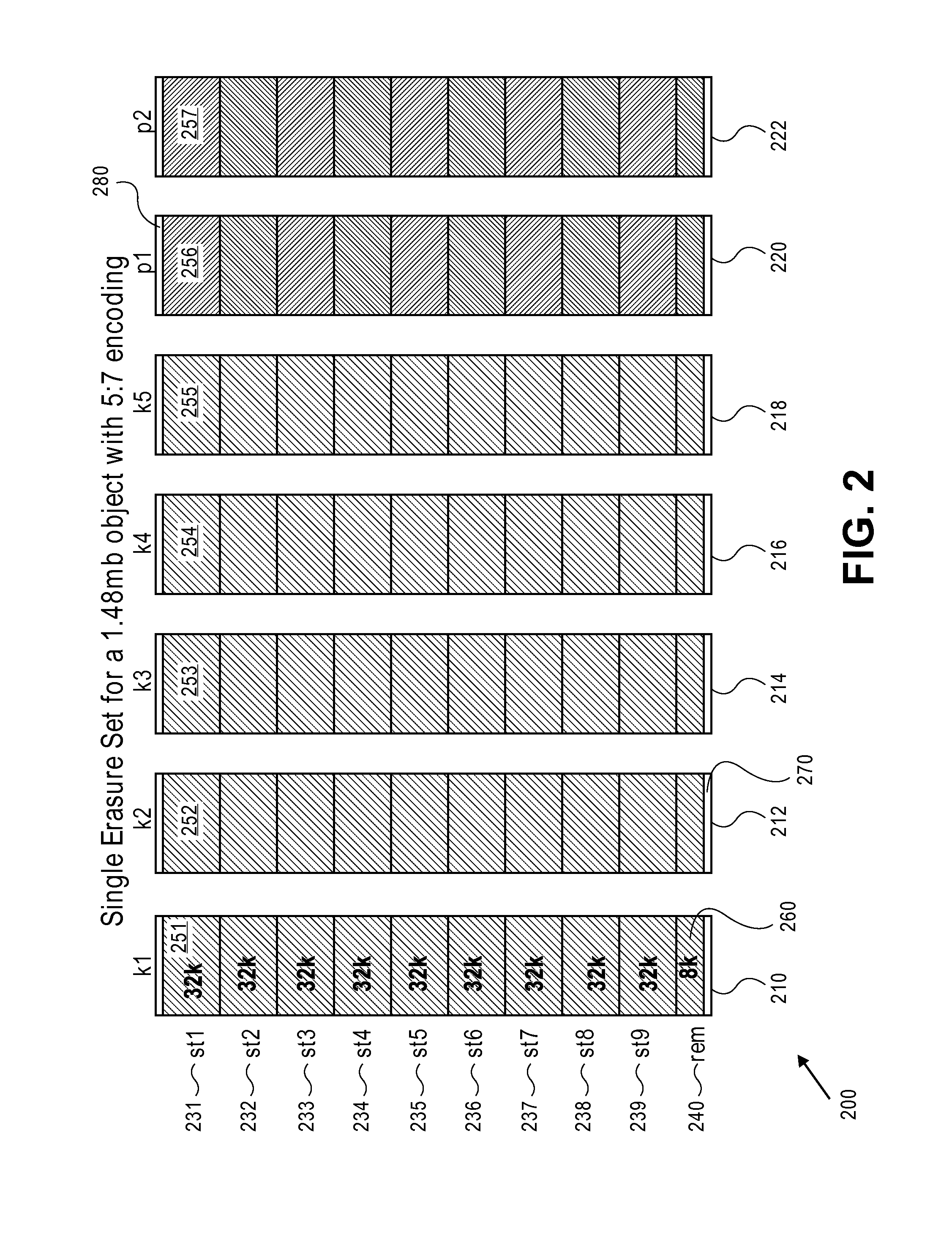
[0043]Included within each manifest is a metadata section 310, at least one erasure set 340 and any number of other erasure sets 380. Of course, the number of erasure sets represented within the manifest depends upon the size of the data object, the size of each segment, and the encoding scheme used. Section 312 of the manifest provides the name of the erasure coding algorithm used and its version number. The specific erasure coding is shown in section 314 and the size of each data block (stripe width) within a segment is shown in section 316. Other information in t...


PUM


Abstract

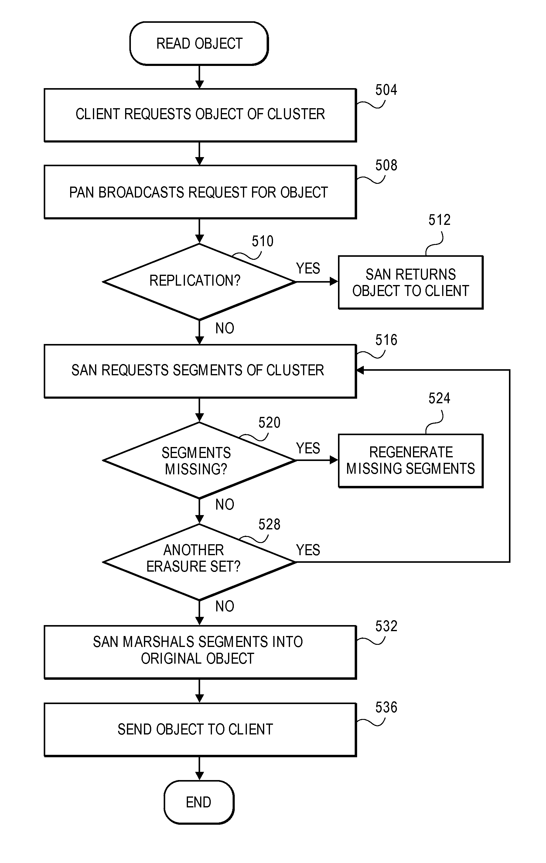
A cluster receives a request to store an object using replication or erasure coding. The cluster writes the object using erasure coding. A manifest is written that includes an indication of erasure coding and a unique identifier for each segment. The cluster returns a unique identifier of the manifest. The cluster receives a request from a client that includes a unique identifier. The cluster determines whether the object has been stored using replication or erasure coding. If using erasure coding, the method reads a manifest. The method identifies segments within the cluster using unique segment identifiers of the manifest. Using these unique segment identifiers, the method reconstructs the object. A persistent storage area of another disk is scanned to find a unique identifier of a failed disk. If using erasure coding, a missing segment previously stored on the disk is identified. The method locates other segments. Missing segments are regenerated.

Description

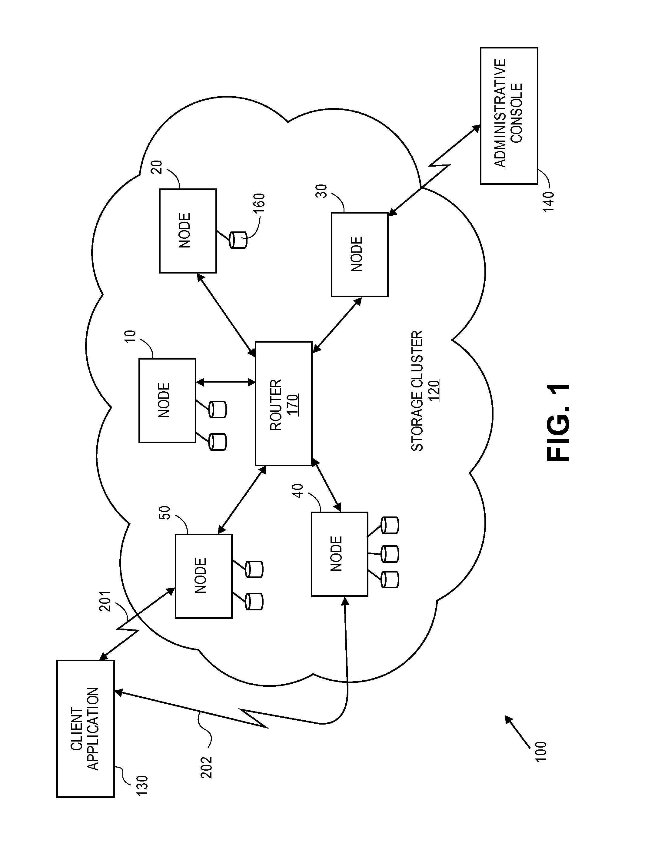
CROSS-REFERENCE TO RELATED APPLICATIONS[0001]This application is related to U.S. patent application Ser. No. 13 / 517,523 filed on the same date herewith, entitled “TWO LEVEL ADDRESSING IN STORAGE CLUSTERS” and to U.S. patent application Ser. No. 13 / 517,525 filed on the same date herewith, entitled “ELIMINATION OF DUPLICATES IN STORAGE CLUSTERS,” both of which are hereby incorporated by reference.FIELD OF THE INVENTION[0002]The present invention relates generally to erasure coding. More specifically, the present invention relates to a combination of erasure coding and replication in a fixed-content storage cluster and to volume failure recovery when using erasure coding.BACKGROUND OF THE INVENTION[0003]Traditionally, storage provided in a storage cluster (such as by using a redundant array of independent nodes, or RAIN) is made reliable against hardware failure either through replication of stored objects or erasure coding of stored objects. The former has the advantage that the same ...

Claims


Application Information

Patent Timeline
Patent Type & Authority Patents(United States)
IPC IPC(8): G06F11/14G11C29/00G06F11/10H03M13/05H03M13/25
CPCH03M13/05H03M13/25G06F11/10G06F11/14H03M13/251H03M13/2707H03M13/353H03M13/356H03M13/373H03M13/3761G06F3/0605G06F3/0632G06F3/0667G06F3/067G06F3/0619G06F3/065G06F11/1076G06F3/064G06F3/0683H04L67/1095H04L67/1097
Inventor BAKER, DONCARPENTIER, PAUL R. M.KLAGER, ANDREWPIERCE, AARONRING, JONATHANTURPIN, RUSSELLYOAKLEY, DAVID
Owner DATACORE SOFTWARE
Learn More