Container for pressurized fluids

a technology for containers and fluids, applied in the field of containers, can solve the problems of affecting the relative transversal displacement of containers, allowing the occurrence of undesirable shocks between the side walls, and damage to the outer finishing of the cylindrical side walls of these containers, and achieve the effect of preventing relative transversal displacemen

Inactive Publication Date: 2014-08-12
BRASILATA S A EMBALAGENS METALICAS
View PDF8 Cites 1 Cited by
  • Summary
  • Abstract
  • Description
  • Claims
  • Application Information

AI Technical Summary

Benefits of technology

[0009]As a function of the limitations of stacking the known containers for pressurized fluids, it is an object of the present invention to provide a type of container which is structurally resistant to high inner pressure, without requiring increasing the sheet metal thickness and which can be safely stacked in a vertical position, directly over an identical container stacked below, both in a condition deprived of the spray valve and upper lid and in a condition in which the already filled containers are provided with the usual upper lid covering the spray valve.
[0014]The construction proposed herein allows the bottom wall of a container to be fitted and locked, in the radial direction, on the upper double seam of a container, still without the spray valve and the lid, and which is disposed immediately below in a stack or also on the upper edge region of a lid fitted on said inferiorly disposed container, preventing the relative transversal displacement between the two containers.

Problems solved by technology

The known container construction mentioned above, presenting lower and upper walls in the form of a spherical dome, causes difficulty in stacking said containers in the vertical position, with the bottom wall of a container seating onto the upper wall or on the lid of the container immediately below in the stack.
Although allowing stacking multiple layers of vertically disposed containers, this prior art solution presents the inconveniences of requiring the provision of the intermediary support sheet and not providing a mutual retention or locking against relative horizontal (radial) displacements between the containers stacked on top of one another, permitting the occurrence of undesirable shocks between the side walls, which are externally lithographed with the promotional messages that identify the stored product and its manufacturer.
These shocks can damage the outer finishing of the cylindrical side wall of these containers, particularly when the lower double seam of a container hits the side wall of an adjacent container.
The solution consists in deforming the lower double seam inwards, to maintain it inside the axial projection of the cylindrical contour of the can, which requires an additional and relatively complex operation in the production of said containers.
Besides not allowing a safe vertical stacking between the containers still deprived of the spray valve, as a function of the spherical dome shape of the bottom wall and the upper wall, particularly the shape of the bottom wall, the containers of the type considered herein are not safely vertically stackable as well, after receiving the spray valve and the known upper lid in the filler.
Although the upper lid presents a general cylindrical inverted cup shape, with a side wall fitted around the upper double seam and with a flat top wall covering, with an axial gap, the upper wall and the valve already installed therein, the spherical dome shape of the bottom wall of the container prevents it from being safely fitted, with radial locking, on the lid of a container disposed immediately below, in a vertical stack.
This feature of the current containers jeopardizes and increases the cost of packaging and transportation of the containers, from the filler to the point of sale, and further leads to limitations in the arrangement of the containers to be displayed to the final consumer, for example, in gondolas or shelves.

Method used


Image

  • Container for pressurized fluids
  • Container for pressurized fluids
  • Container for pressurized fluids

Examples


second embodiment

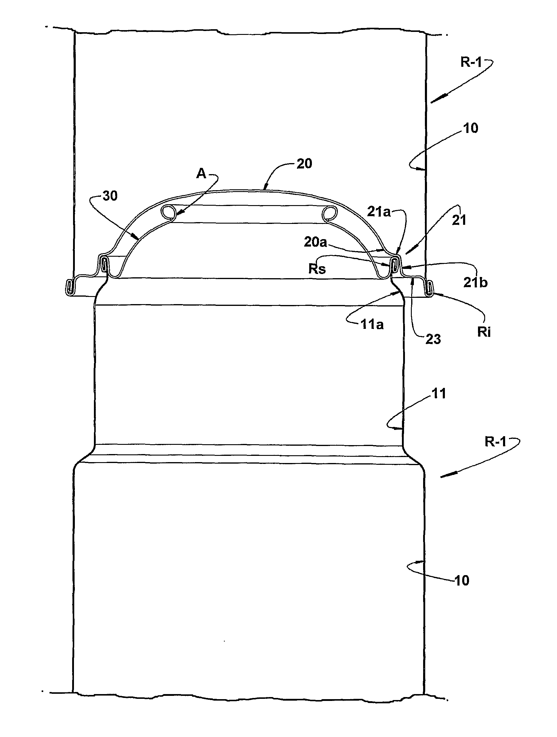
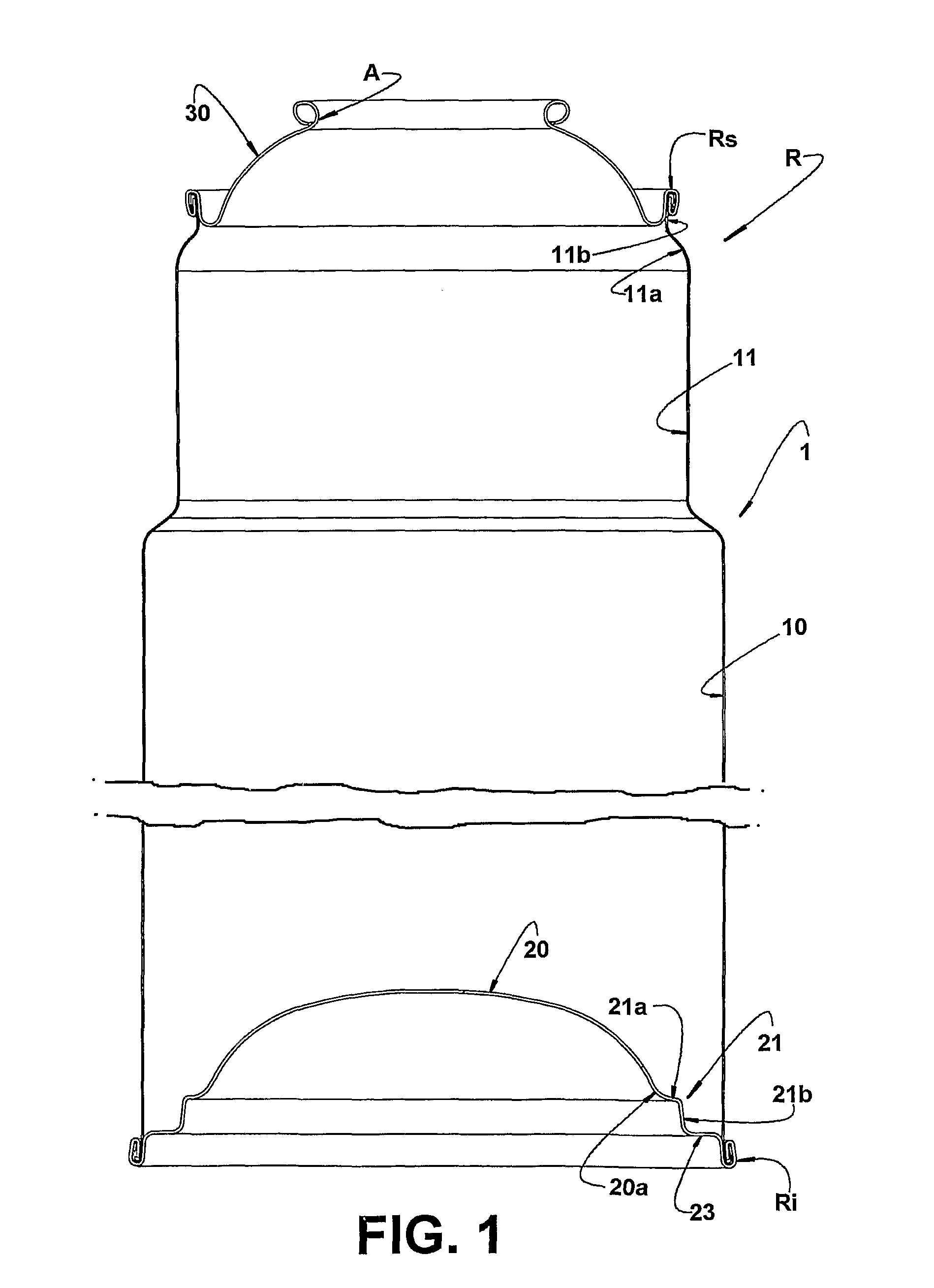
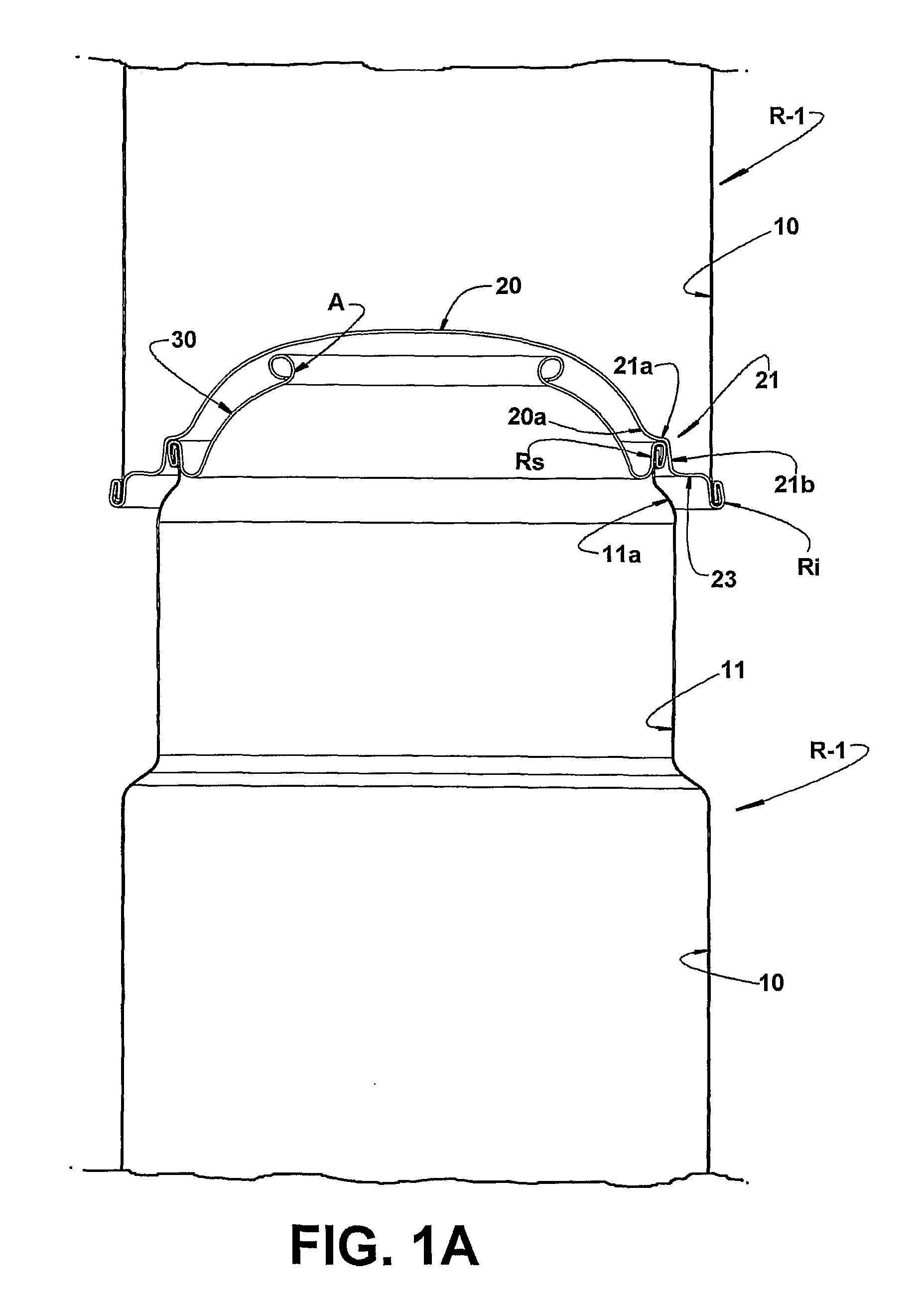
[0040]As can be seen, the frusto-conical shape of the guiding skirt portion 21b of the seating region 21, allows the latter to be seated around the lid 40, producing a mutual radial locking between the two containers, even considering the dimensional tolerance variations of the elements constitutive of these containers. Thus, the guiding skirt portion 21b of frusto-conical shape presents the smaller inner diameter smaller than the outer diameter of the side wall 41 of the lid 40 and the larger inner diameter larger than the inner diameter of said side wall 41 of the lid 40, in an upper edge region of the latter, in which it is connected to the top wall 42. FIGS. 2, 2A, 2B and 2C illustrate a second constructive form for the bottom wall 20 of the container R. In this second embodiment, the bottom wall 20 presents at least three seating regions 21 which are equally and angularly spaced apart along the circular contour of the container R, said seating regions 21 projecting downwards fr...

first embodiment

[0042]It should be understood that the seating of the multiple seating regions 21, on the upper double seam Rs or on the lid 40 of a container R disposed immediately below in a vertical stack of said containers, is carried out exactly in the same way already described in relation to the bottom wall 20. However, it should be considered that the support region between the bottom wall of the upper container and the upper double seam Rs or the lid 40 of the lower container is defined not around the whole circumference of the containers, but only in the circumferential extensions defined in each of the seating regions 21.

[0043]As illustrated in the enclosed drawings, and independently of the embodiment of the seating region 21, either single or multiple, its incorporation, in a single piece, to the bottom wall 20 is made through the arched interconnection regions, in order to prevent stress concentrations which are harmful to the resistance required for said bottom wall 20 as a function ...


PUM


Abstract

A container having a tubular body including a side wall, a bottom wall in the form of a spherical dome projecting to the interior of the container, and an upper wall in the form of an annular spherical dome, inferiorly attached to the side wall by an upper double seam. The bottom wall includes at least one seating region having a predetermined circumferential extension along a plane extending transversely with respect to an axis of the container and being axially spaced inwardly within the side wall of the container, the seating region being configured to be fitted around a respective circumferential extension a upper double seam of an identical and adjacent container inferiorly disposed in a vertical stack, and axially seated on said upper double seam, so as to define a single contact region between two vertically stacked containers.

Description

CROSS-REFERENCE TO RELATED APPLICATIONS[0001]This application is a US National Phase Application under 35 U.S.C. §371 of International Patent Application No. PCT / BR2008 / 000270 filed Sep. 3, 2008, which claims priority from Brazilian Patent Application No. PI0703846-1, filed Sep. 3, 2007, each of which are hereby incorporated by reference in their entireties. The International Application published in the English language as WO 2009 / 030009 A1 on Mar. 12, 2009.FIELD OF THE INVENTION[0002]The present invention refers to a container constructed in sheet metal and of the type usually used as a device for containing and applying gas pressurized fluids, by means of a spray valve, as it occurs with the aerosols. The invention is particularly related to the construction of the container lower wall, which is usually configured in an inwardly-facing spherical dome, so that the container can be safely vertically stacked onto the other containers presenting the same construction.PRIOR ART[0003]T...

Claims


Application Information

Patent Timeline
Patent Type & Authority Patents(United States)
IPC IPC(8): B65D85/62B65D21/02B65D83/38
CPCB65D83/38B65D21/0231
Inventor ALVARES, ANTONIO CARLOS TEIXEIRADA CUNHA, SILVERIO CANDIDO
Owner BRASILATA S A EMBALAGENS METALICAS
Why Eureka
Try Eureka