Photovoltaic array system, photovoltaic device thereof, and frame element of photovoltaic device thereof
a photovoltaic array and photovoltaic array technology, applied in the field of frame elements, can solve the problems of increasing labor cost and manufacturing cost for making the outer frame, not only wasteing the material of the outer frame, and increasing the total weight of the photovoltaic device by a large amoun
- Summary
- Abstract
- Description
- Claims
- Application Information
AI Technical Summary
Benefits of technology
Problems solved by technology
Method used
Image

Examples
Embodiment Construction
[0025]In the following detailed description, for purposes of explanation, numerous specific details are set forth in order to provide a thorough understanding of the disclosed embodiments. It will be apparent, however, that one or more embodiments may be practiced without these specific details. In other instances, well-known structures and devices are schematically shown in order to simplify the drawings.
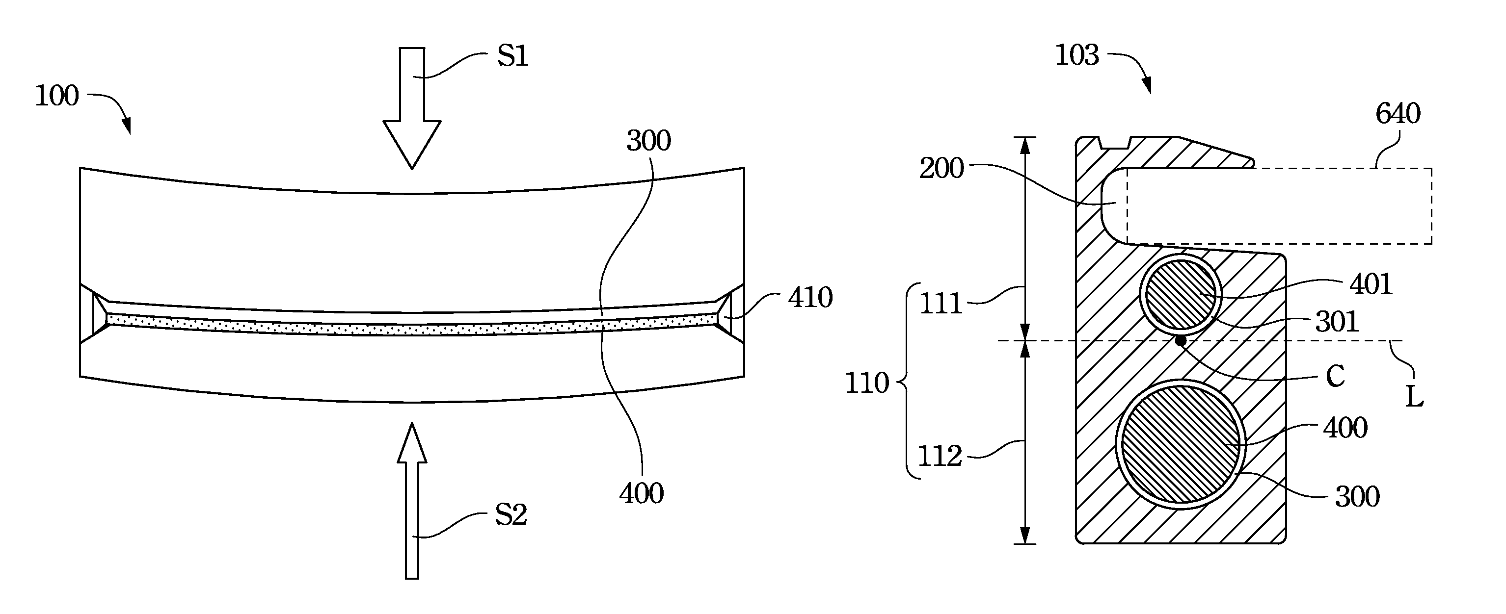
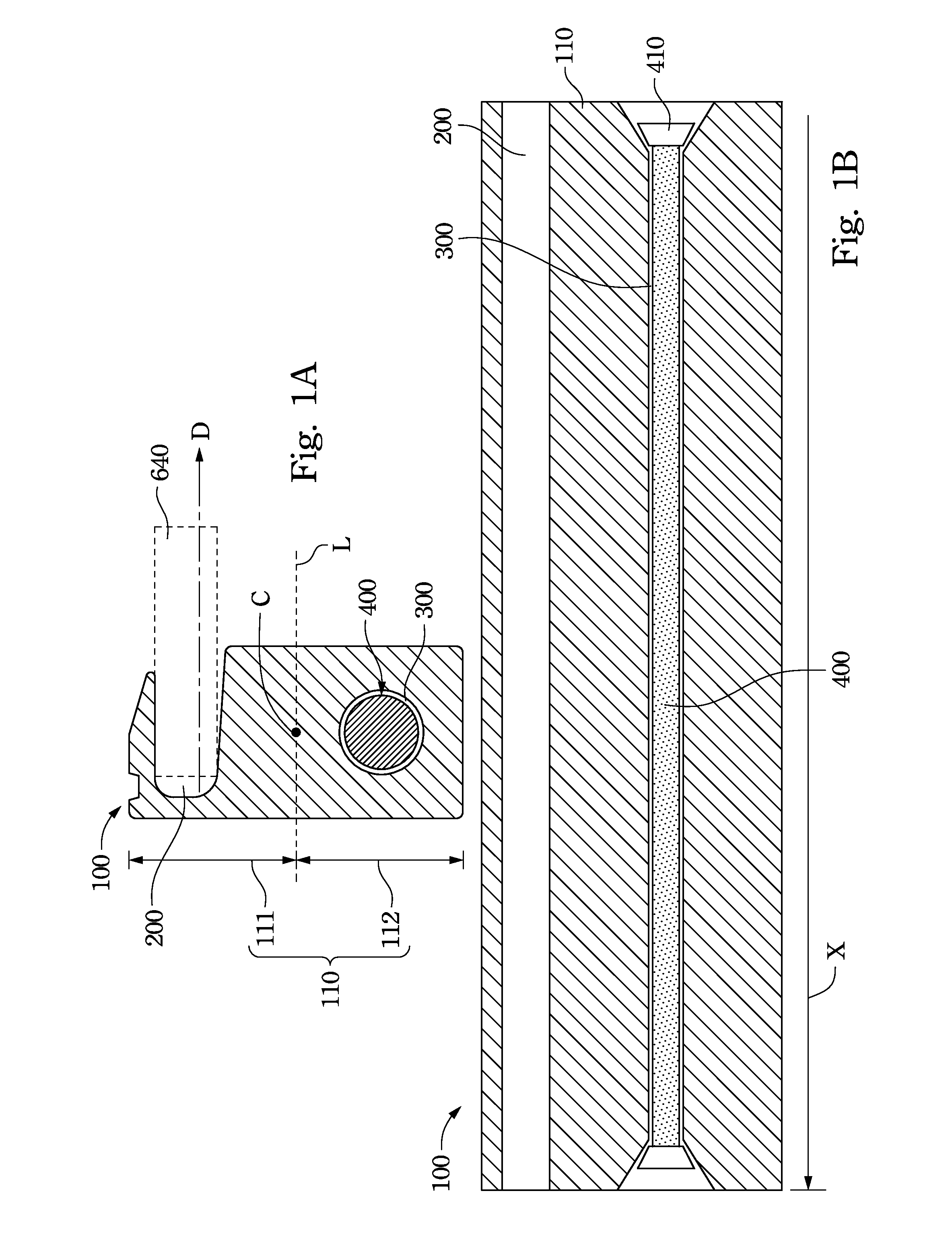
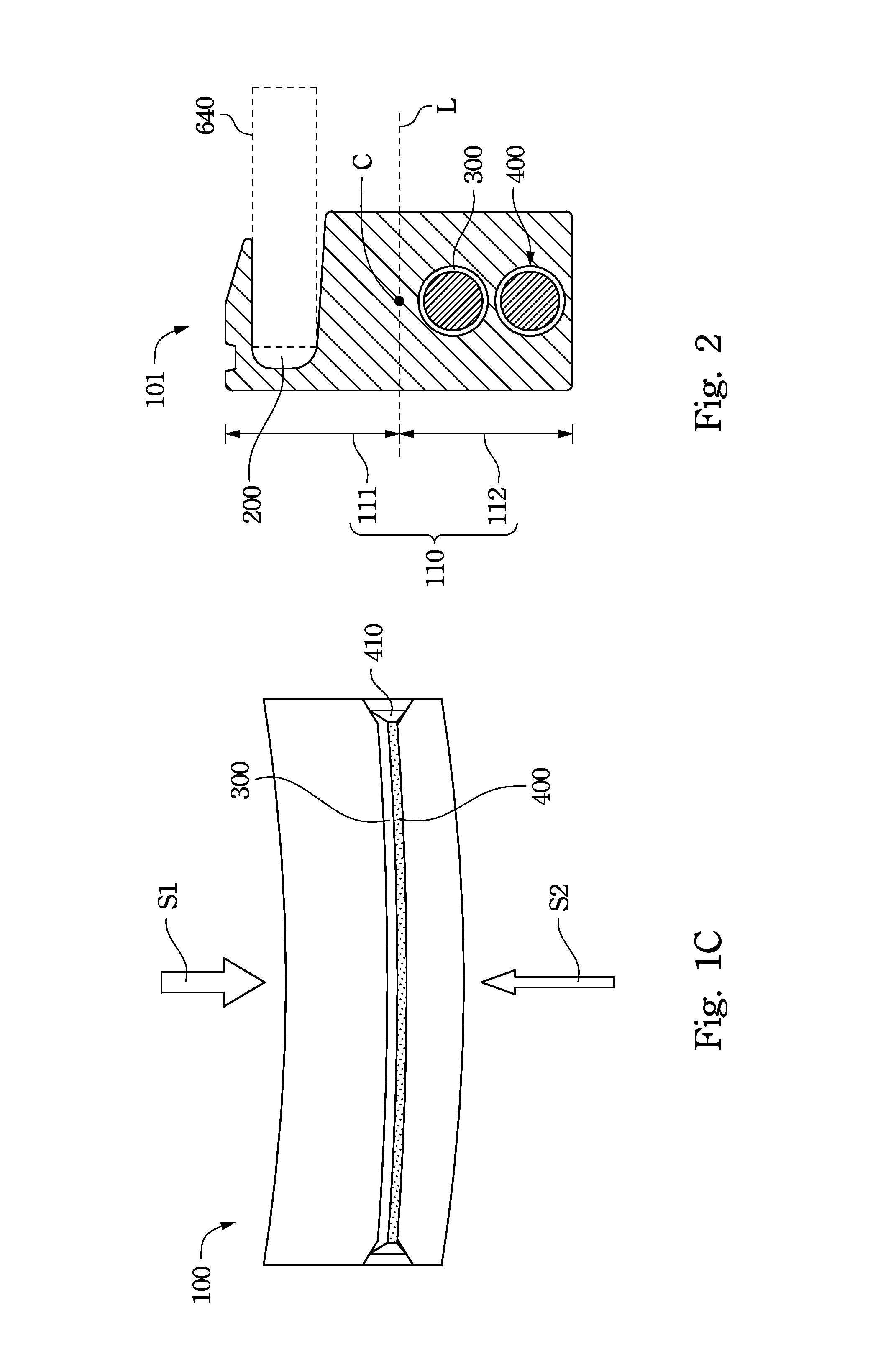
[0026]According to the present disclosure, a frame element of a photovoltaic device is longitudinally penetrated by at least one metal wire, and the extending direction of the metal wire is the same as the extending direction of one side of a photovoltaic panel of the photovoltaic device. As such, when the photovoltaic device is pressed by an external force, the photovoltaic device is not easy to be bent and deformed due to the metal wire having the capability of stretch resistance and resisting the external pressure.
[0027]Reference is now made to FIG. 1A and FIG. 1B. FIG. 1A is a ...
PUM
 Abstract
Description
Claims
Application Information
 - R&D
- Intellectual Property
- Life Sciences
- Materials
- Tech Scout
- Unparalleled Data Quality
- Higher Quality Content
- 60% Fewer Hallucinations
Browse by: Latest US Patents, China's latest patents, Technical Efficacy Thesaurus, Application Domain, Technology Topic, Popular Technical Reports.
© 2025 PatSnap. All rights reserved.Legal|Privacy policy|Modern Slavery Act Transparency Statement|Sitemap|About US| Contact US: help@patsnap.com