Elastomeric plain bearing having switchable rigidity

a technology of elastomeric bush and rigidity, which is applied in the direction of shock absorbers, machine supports, mechanical equipment, etc., can solve the problems that elastomer cannot move into the above-mentioned intermediate spaces, and achieve the effect of preventing the frequency in the acoustic range caused by stiffness or high volume yieldability

Active Publication Date: 2014-08-19
AUDI AG
View PDF34 Cites 2 Cited by
  • Summary
  • Abstract
  • Description
  • Claims
  • Application Information

AI Technical Summary

Benefits of technology

[0014]The invention is based on the concept that the stiffness increases with the ratio between the bound and the free surface of the elastomer. The fact that rubber and comparable elastomers are incompressible plays an important role. When the working chamber does not contain fluid, the free surface of the elastomer is determined in the region of this chamber by the outer end faces of the segments of the elastomeric bearing body formed in the switching packet. When the elastomer is deflected, it can move out of the way into the free spaces formed by the chamber sections of the respective working chamber which project into and segment the bearing body. The stiffness in the region of this working chamber is hereby comparatively small. However, when the working chamber is filled with a fluid and hence with an incompressible medium, the elastomer can no longer move into the aforementioned intermediate spaces. Instead, both the elastomer of the segments of the bearing body as well as the fluid tend to expand, in competition with one another, into the free spaces formed by the radially extending chamber sections of the working chambers under radial load. The segments and the elastomeric webs, respectively, between the radial chamber sections of the working chambers are supported on both sides by the pressure of the fluid, causing small expansions in the elastomer in the region of these segments. However, the spreading or changeability of the radial stiffness that can be attained for a defined chamber pressure in the region of the corresponding working chamber increases with increasing ratio of the free surface of the elastomer before and after a working chamber has been filled with the fluidic damping means 22 (as shown in FIGS. 3 and 4). This also implies: the greater the ratio of the free surfaces before and after the working chamber is filled with the fluid at the required stiffness spreading, the smaller is the expected chamber pressure. With the structure of the working chambers according to the invention and the segmentation of the bearing body then attained in the switching packet, the available free surface of the elastomer is increased. As result, as described above, the load of the elastomer is relatively small even at a high stiffness spreading, thus improving the endurance and / or the durability of the bearing.
[0015]In another possible embodiment of the bearing according to the invention, the stiffness of the bearing can be switched by blocking or temporarily unblocking a channel 24 (as shown in FIGS. 3-5) that connects the working chambers 4, 4′ (as shown in FIGS. 3-5) with one another. According to another embodiment, the fluid exchange between the working chambers 4, 4′ and at least one additionally provided equalization chamber 26 with a high volume yieldability which is arranged axially below and / or above (as shown in FIG. 4) the working chambers 4, 4′, can be blocked or temporarily unblocked by a switching process. The aforementioned equalization chamber(s) 26 is / are chambers, comparable to the equalization chambers known from engine mounts, having a greater volume than the working chambers 4, 4′. Due to the comparatively large volume of an equalization chamber 26, fluid which flows from one working chamber 4 or 4′ into the equalization chamber 26 does basically not increase the chamber pressure of the equalization chamber 26. Conversely, fluid flowing into the working chambers 4, 4′ immediately increases the pressure in the working chambers 4, 4′. By automatically blocking and temporarily unblocking the channels 24, 28 (as shown in FIG. 4) connecting the equalization chamber(s) 26 with the working chambers 4, 4′, for example when used in an automobile, depending on the driving and / or load situation based on information from the vehicle, a bush bearing formed in this manner can change between two basic switching states. In the first switching state of the bush bearing, the inflow f3 (as shown in FIG. 4) of fluid from the respective equalization chamber 26 is blocked for both working chambers 4, 4′. The bush bearing has in this switching state, where the working chambers 4, 4′ are emptied of fluid, a small radial stiffness. Conversely, the bush bearing has a high radial stiffness in a second switching state, where the outflow of fluid into the equalization chamber is blocked for both working chambers 4, 4′ filled with fluid.
[0017]The channel formed between the working chambers or the channel connecting the working chambers with an equalization chamber preferably have a considerable width compared to their length, so that the respective channel with the yieldability of the working chambers goes into resonance as late as possible, i.e., at higher frequencies, to prevent frequencies in the acoustic range caused by stiffness in or on a channel from being transmitted hard. According to a particularly advantageous embodiment of a bush bearing formed with at least one compensation chamber having high volume yieldability, comparable with the chamber of an engine mount, the ratio between the channel width and the length of the channel connecting the equalization chamber with a working chamber is preferably equal to 1 or greater.
[0018]According to a feasible improvement of the invention, additional inserts, which also extend in the axial direction, or intermediate plates, may be arranged in the elastomer of the inner spring packet operating as working packet. In this way, the shear stiffness becomes relatively small in spite of a high compressive stiffness.

Problems solved by technology

However, when the working chamber is filled with a fluid and hence with an incompressible medium, the elastomer can no longer move into the aforementioned intermediate spaces.

Method used


Image

  • Elastomeric plain bearing having switchable rigidity
  • Elastomeric plain bearing having switchable rigidity
  • Elastomeric plain bearing having switchable rigidity

Examples


Embodiment Construction

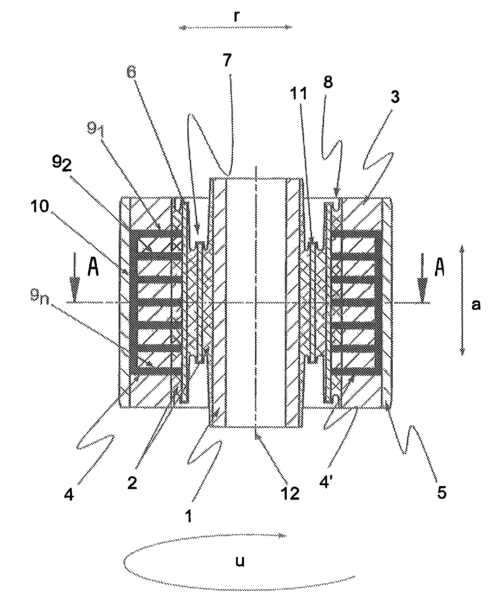
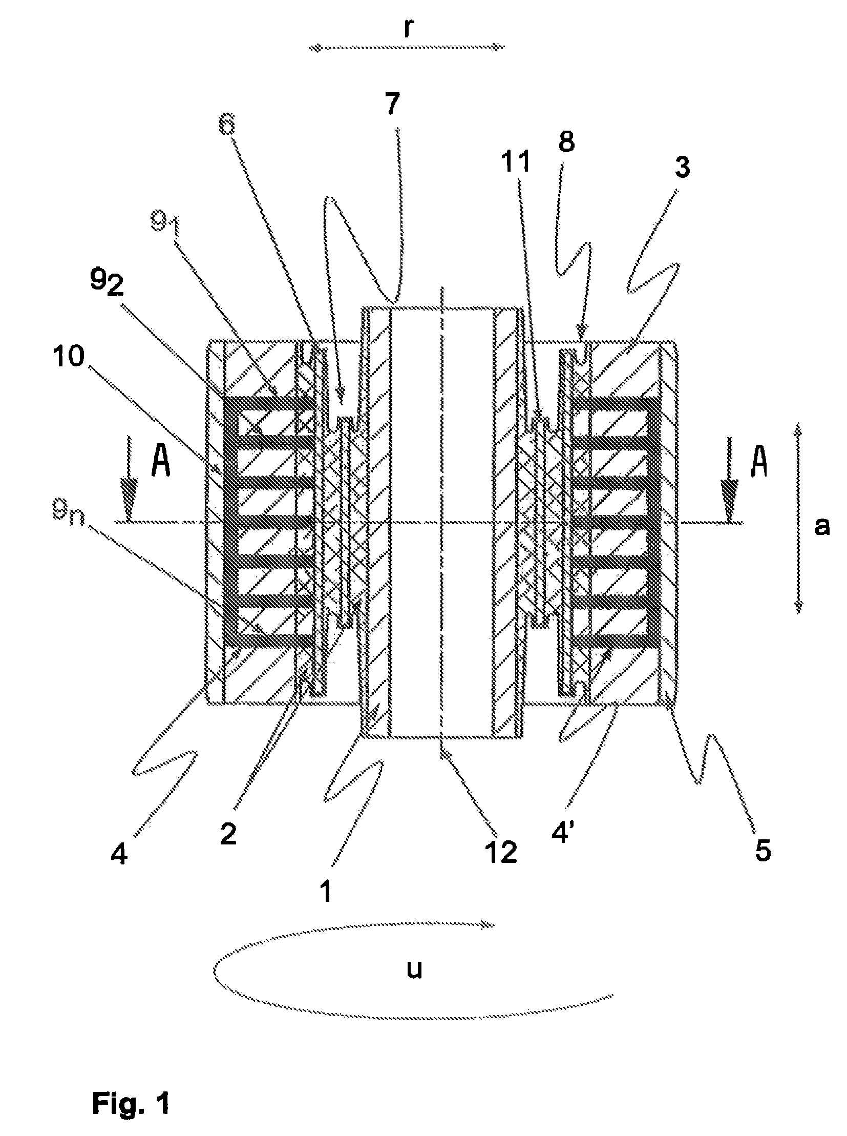
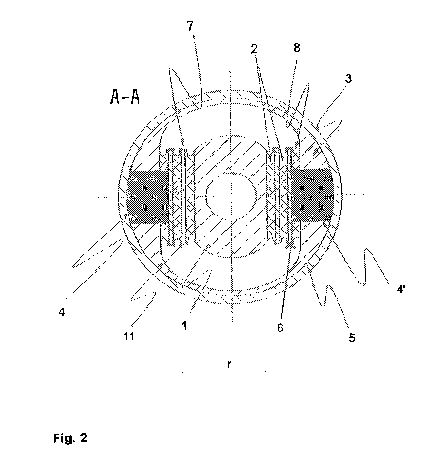
[0026]FIG. 1 shows a cross-sectional view of an elastomeric bush bearing constructed according to the invention, wherein the actuators 29 for switching the stiffness are shown in FIGS. 3-5. The drawing is only intended to once more describe the particular geometry of the bearing constructed according to the invention and more particularly describe the special configuration of the working chambers 4, 4′. The bearing includes the metallic inner part 1, the elastomeric bearing body 2, the preferably also metallic outer part 3, and the likewise preferably metallic bearing sleeve 5 receiving the aforementioned parts. The elastomeric bearing body 2 is arranged between the inner part 1 and the outer part 3 and connected with the therewith by the vulcanization. Furthermore, an intermediate plate 6 which extends parallel to the bearing axis 12 is vulcanized into the bearing body 2, dividing the bearing body into two spring packets 7, 8. The inner spring packet 7 operates as a working packet,...


PUM


Abstract

A bearing body (2) is divided in the radial direction (r) by at least one insert (6) arranged in the bearing body (2) parallel to the bearing axis (12) into at least two spring packets (7, 8) having an outer switching packet (8). Each of the working chambers (4, 4′) is divided into several chamber sections (91-9n) extending in the radial direction (r) and into at least one chamber section (10) extending in the axial direction (a) and connecting the chamber sections (91-9n) with one another. The elastomeric bearing body (2) is segmented in the switching packet (8) in the axial direction (a) by the chamber sections (91-9n) protruding into the elastomeric bearing body (2).

Description

[0001]This is an application filed under 35 USC §371 of PCT / DE2010 / 050012, claiming priority to DE 102009 001 757.1 filed on Mar. 23, 2009.BACKGROUND OF THE INVENTION[0002](1) Field of the Invention[0003]The invention relates to an elastomeric bush or plain bearing with a changeable radial rigidity or stiffness. The bearing can be switched between a state with a rather low stiffness and a state with a comparatively higher stiffness. The bearing consists substantially of a preferably tubular metallic inner part, a cylindrical outer part and an elastomeric bearing body arranged between the inner part and the outer part and connected at least with the inner part by vulcanization, and a bearing sleeve receiving the aforementioned elements of the bearing. At least two chambers for receiving a fluid are arranged in the bearing body.[0004](2) Description of Related Art[0005]Elastomeric bush bearings are widely employed in particular in the automotive industry and are preferably used for su...

Claims


Application Information

Patent Timeline
Patent Type & Authority Patents(United States)
IPC IPC(8): F16F5/00
CPCF16F13/1418F16F13/1427F16F13/28
Inventor LOHEIDE, STEFANSIEMER, HUBERTCONRAD, THOMAS
Owner AUDI AG
Why Eureka
Try Eureka