Sheet conveying apparatus, printing apparatus, and processing apparatus
a technology of conveying apparatus and printing apparatus, applied in the direction of thin material handling, article separation, function indicators, etc., can solve the problems of image quality degradation and degraded printed image quality, and achieve the effect of reducing image quality degradation
- Summary
- Abstract
- Description
- Claims
- Application Information
AI Technical Summary
Benefits of technology
Problems solved by technology
Method used
Image
Examples
first embodiment
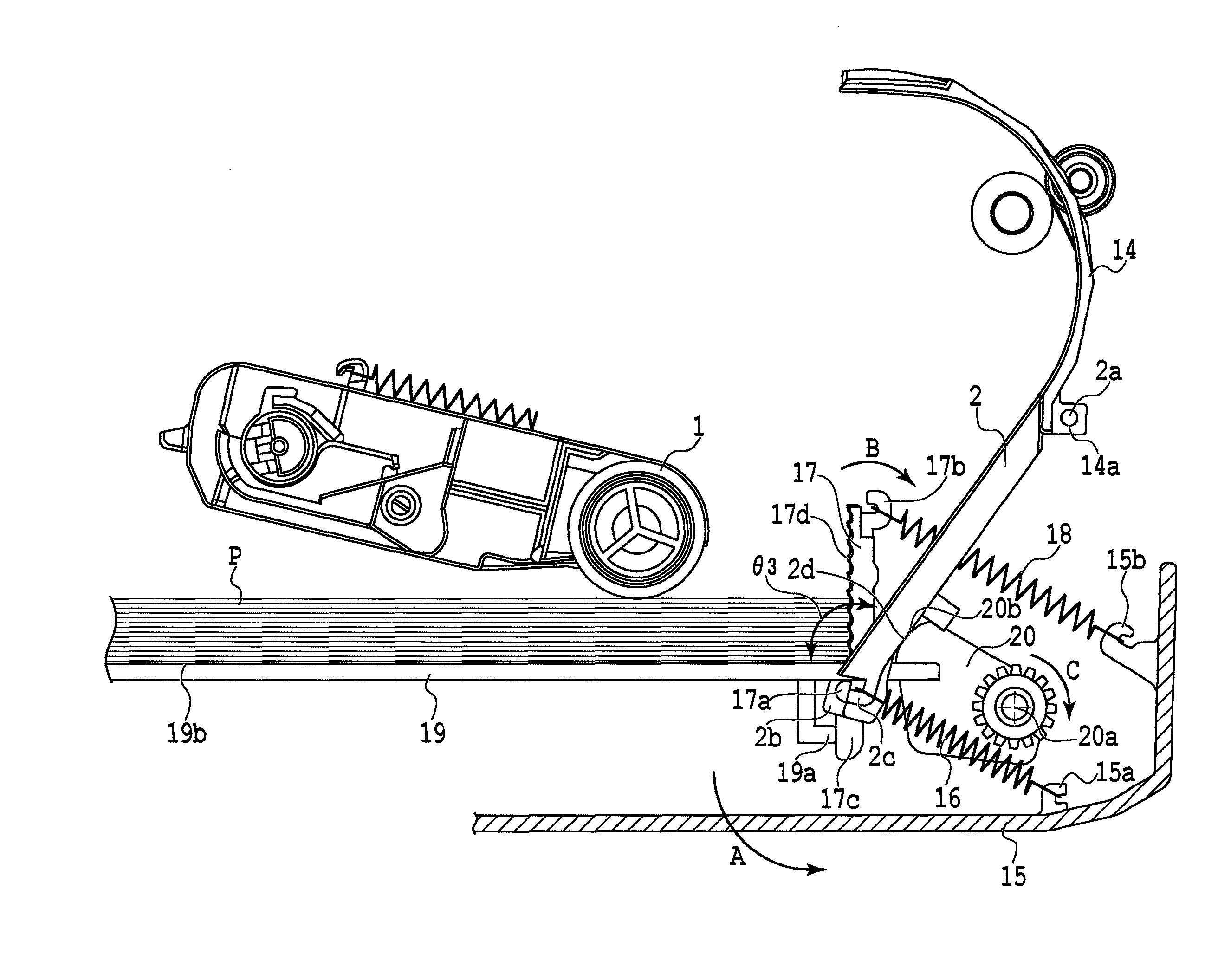
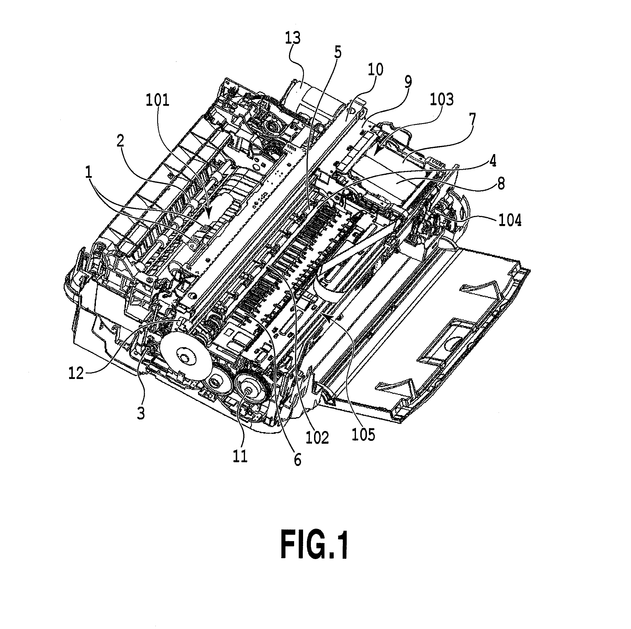
[0024]FIG. 1 is a perspective view showing an inkjet printing apparatus according to the present embodiment. Sheets stacked in a sheet conveying unit 101 is separated one by one by the separation of the sheet stacked on the uppermost portion through the use of: a sheet conveying roller 1 serving as a sheet conveying unit that is driven by a sheet conveying motor and conveys the sheet; and a separation slope 2. The separated sheets are conveyed to a conveyance unit 102. The sheet conveyed to the conveyance unit 102 is conveyed on a platen 6 by a sheet conveying roller 4 driven by a conveyance motor 3, and by pinch rollers 5.
[0025]A printing mechanism unit 103 prints an image and the like on the sheet based on image information. Specifically, a printing head 7 and a printing head 8 are mounted on a carriage 9, the carriage 9 is guided and supported by a guide rail 10, and the carriage 9 reciprocatingly moves n the direction (main-scanning direction) perpendicular to the conveyance dir...
second embodiment
[0067]In the first embodiment, the state of the separation slope 2 is switched based on the information of a printing driver. However, in the present embodiment, the separation slope is switched by torque information of a sheet conveying motor driving source when the end portion in the downstream direction in the conveyance direction of a sheet abuts the separation slope 2.
[0068]FIG. 9 is a flow chart showing a flow from an instruction of the start of printing on a sheet to the end of printing in the present embodiment. Hereinafter, parts different from the flow of printing in the first embodiment will be mainly described.
[0069]In the present embodiment, when an instruction of the start of printing on the sheet P is performed via the PC or the like from a user, the separation slope 2 is switched to the state where a sheet having low rigidity is conveyed (step S17). Then, after whether or not there is no sheet is detected (step S5), and the presence or absence of the overlapped conve...
third embodiment
[0076]In the above-described embodiments, although the sheet tip position determining member 17 is configured to be rotatably attached to the separation slope 2, the present invention may not be configured that way.
[0077]FIG. 10 is an enlarged view showing a sheet tip position determining member and the periphery thereof according to the present embodiment. In a sheet tip position determining member 21 according to the present embodiment, a rotation center shaft 21a is rotatably inserted into a rotation center hole 22a of a stacking portion 22. Then, a cam portion for moving also the sheet tip position determining member 21 is provided in a rotating cam for performing the movement of the separation slope 2, and thus the sheet tip position determining member 21 is moved so that the position of the sheet tip position determining member 21 and the disposition of the separation slope 2 is the same as the position of the sheet tip position determining member 17 and the disposition of the...
PUM
| Property | Measurement | Unit |
|---|---|---|
| distance | aaaaa | aaaaa |
| angle | aaaaa | aaaaa |
| distance | aaaaa | aaaaa |
Abstract
Description
Claims
Application Information
 - R&D
- Intellectual Property
- Life Sciences
- Materials
- Tech Scout
- Unparalleled Data Quality
- Higher Quality Content
- 60% Fewer Hallucinations
Browse by: Latest US Patents, China's latest patents, Technical Efficacy Thesaurus, Application Domain, Technology Topic, Popular Technical Reports.
© 2025 PatSnap. All rights reserved.Legal|Privacy policy|Modern Slavery Act Transparency Statement|Sitemap|About US| Contact US: help@patsnap.com


