Technique for optimizing skew in the presence of tape motion

a technology of skew and motion, applied in the direction of recording signal processing, instruments, maintaining head carrier alignment, etc., can solve the problems of skew reading change, read elements can no longer accurately read back data, read elements may no longer be able to read back data from magnetic tape, etc., to achieve accurate skew adjustment, optimize skew, and optimize skew

Inactive Publication Date: 2014-08-19
IBM CORP
View PDF15 Cites 0 Cited by
  • Summary
  • Abstract
  • Description
  • Claims
  • Application Information

AI Technical Summary

Benefits of technology

[0009]Consistent with the foregoing, a method for accurately adjusting skew in the presence of tape motion is disclosed herein. In one embodiment, such a method includes performing a calibration run of magnetic tape in a tape drive. During the calibration run, the method records skew readings at selected intervals. The method then finds a range associated with the skew readings, such as by finding a high and low skew reading. The method then finds a center point of the range, and a difference between the center point and a desired center point. The method then applies the difference to each recorded skew reading to generate a target skew reading for each recorded skew reading. The method generates a skew error signal that reflects the difference between each recorded skew reading and each corresponding target skew reading. The skew error signal will generally be consistent even as the tape moves, thereby allowing a technician to easily adjust and optimize the skew.

Problems solved by technology

However, if the misalignment between the read elements and the center of the written tracks is enough, a point may be reached where the read elements can no longer accurately read back the data.
As alluded to above, if the skew is large enough, the read elements may no longer be able to read back data from the magnetic tape.
Unfortunately, shifts in the tape stack can cause the skew readings to change as the magnetic tape traverses across the head.
Thus, a technician may have difficulty finding an optimal angular position for the tape head relative to the magnetic tape.

Method used


Image

  • Technique for optimizing skew in the presence of tape motion
  • Technique for optimizing skew in the presence of tape motion
  • Technique for optimizing skew in the presence of tape motion

Examples


Embodiment Construction

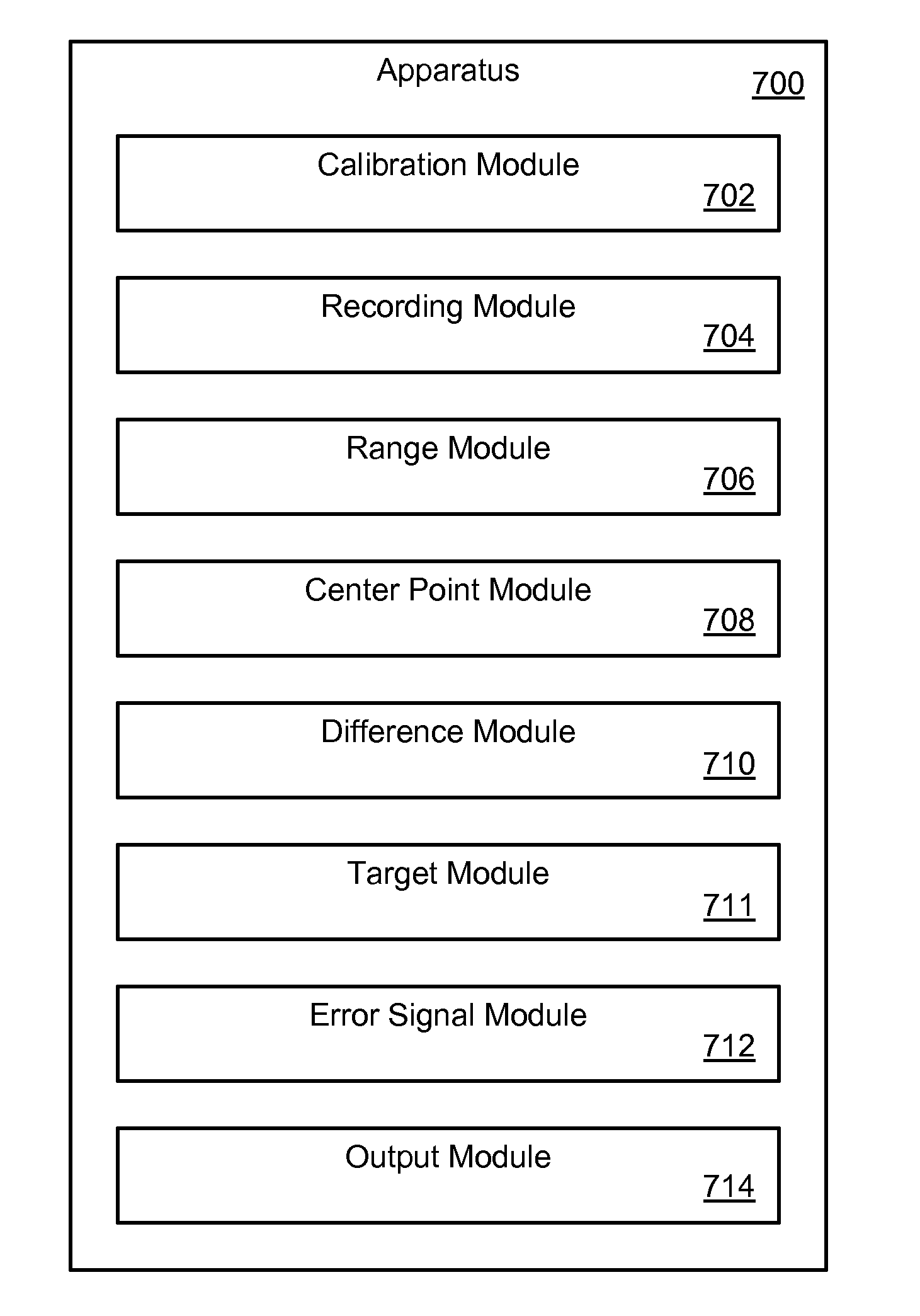
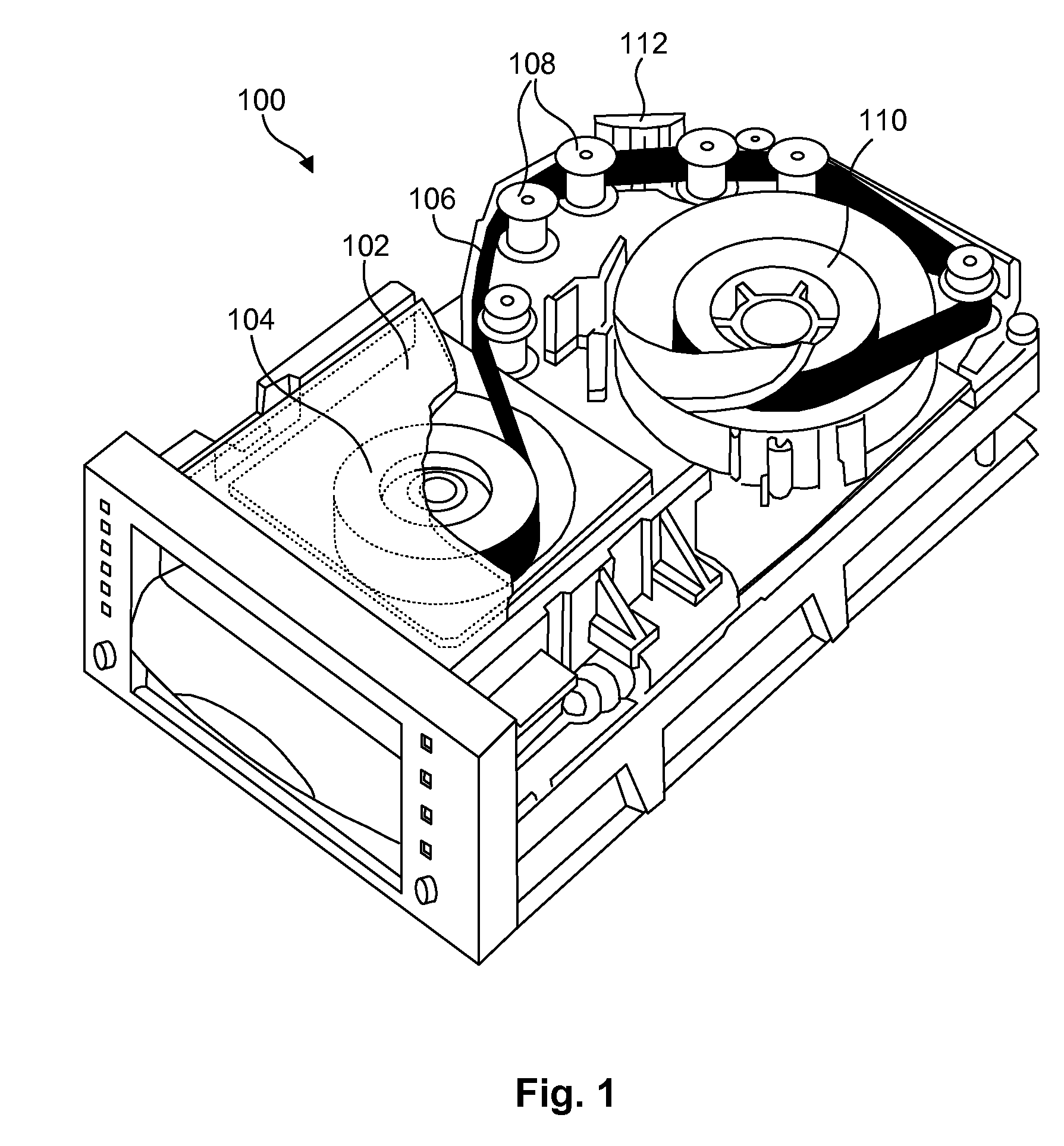
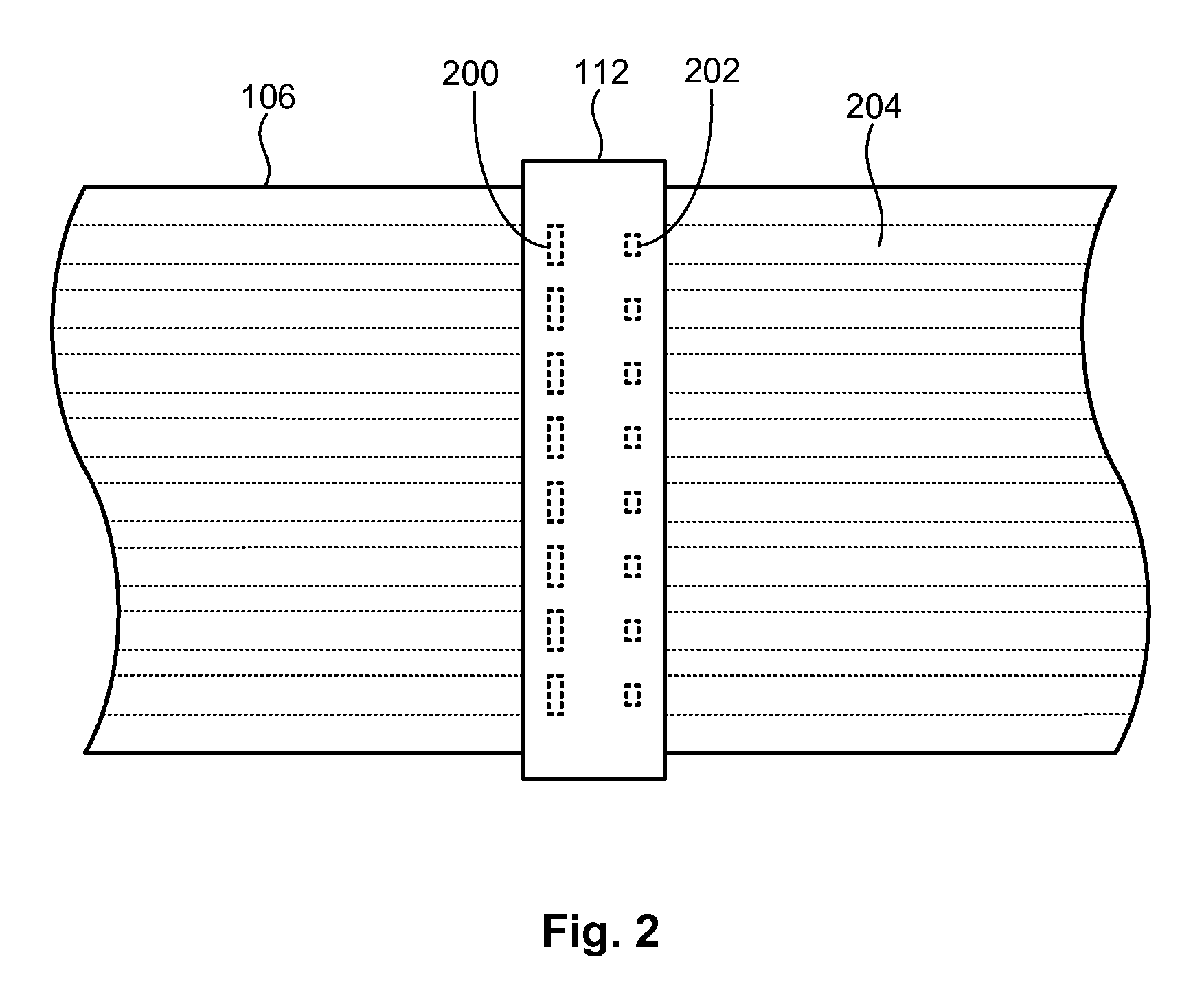
[0021]It will be readily understood that the components of the present invention, as generally described and illustrated in the Figures herein, could be arranged and designed in a wide variety of different configurations. Thus, the following more detailed description of the embodiments of the invention, as represented in the Figures, is not intended to limit the scope of the invention, as claimed, but is merely representative of certain examples of presently contemplated embodiments in accordance with the invention. The presently described embodiments will be best understood by reference to the drawings, wherein like parts are designated by like numerals throughout.

[0022]As will be appreciated by one skilled in the art, the present invention may be embodied as an apparatus, system, method, or computer program product. Furthermore, the present invention may be implemented as a hardware embodiment, a software embodiment (including firmware, resident software, microcode, etc.) configur...


PUM

PropertyMeasurementUnit
magneticaaaaaaaaaa
time intervalsaaaaaaaaaa
distanceaaaaaaaaaa

Abstract

A method for accurately adjusting skew in the presence of tape motion includes performing a calibration run of magnetic tape in a tape drive. During the calibration run, the method records skew readings at selected intervals. The method then finds a range associated with the skew readings, such as by finding a high and low skew reading. The method then finds a center point of the range, and a difference between the center point and a desired center point. The method applies the difference to each recorded skew reading to generate a target skew reading for each recorded skew reading. The method generates a skew error signal that reflects the difference between each recorded skew reading and each corresponding target skew reading. The skew error signal will generally be consistent even as the tape moves, thereby allowing a technician to easily adjust and optimize the skew.

Description

BACKGROUND[0001]1. Field of the Invention[0002]This invention relates to apparatus and methods for reading and writing data on storage media such as magnetic tape.[0003]2. Background of the Invention[0004]In most tape drives, magnetic tape is passed between spools and over guiding elements such as rollers in order to direct the magnetic tape across a read / write head. The read / write head typically includes a number of write elements to write tracks on the magnetic tape, and an equivalent number of read elements to read back data from the magnetic tape as it is written. This allows the written data to be verified as it is written. In order to provide some leeway when reading back data, the read elements are typically narrower than the write elements, and thus narrower than the tracks they are reading back. This allows the read elements to read back data even if they are not exactly centered over the written tracks. However, if the misalignment between the read elements and the center ...

Claims


Application Information

Patent Timeline
Patent Type & Authority Patents(United States)
IPC IPC(8): G11B20/20
CPCG11B5/584G11B20/10388G11B2220/956
Inventor INCH, RANDY CLARKJUDD, KEVIN BRUCE
Owner IBM CORP
Why Eureka
Try Eureka