Pneumatic tire

a technology of pneumatic tires and blocks, applied in the field of pneumatic tires, can solve the problems of increasing the deformation amount of blocks, reducing rigidity, and increasing the probability of cracks in the bottom portions of sipes, so as to achieve high bending rigidity of blocks as a whole, improve durability, and improve the effect of on-ice performan

Active Publication Date: 2014-08-26
THE YOKOHAMA RUBBER CO LTD
View PDF47 Cites 1 Cited by
  • Summary
  • Abstract
  • Description
  • Claims
  • Application Information

AI Technical Summary

Benefits of technology

[0007]An object of the present invention is to solve the above-described problems and to provide a pneumatic tire achieving an enhanced durability, while high on-ice performance is being maintained.
[0014]According to the present invention, in the pneumatic tire wherein the multiple sipes extending in the width direction of the tire are provided at intervals in the circumferential direction of the tire at least in the blocks in the block row formed in the shoulder portion, the multiple sipes provided to the blocks are formed in such a manner that open sipes and closed sipes are alternately arranged in the circumferential direction of the tire and the depth of the open sipes is offset to be shallower than the depth of the closed sipes. Hence, the stress concentrating on the bottom portions of sipes adjacent to each other is dispersed so as not to be concentrated on a line of the same depth. In addition, the depth of the open sipes which have a higher edge effect in the circumferential direction of the tire is made shallower than the closed sipes having a lower edge effect than the open sipes. As a result, a state where the bending rigidity of the blocks as a whole is high is achieved. Thus, while a high on-ice performance is being maintained, the durability can be enhanced.

Problems solved by technology

However, the increase in the number of the sipes results in short intervals of sipes, so that the block rigidity is lowered, and the amount of deformation of the blocks is increased.
For this reason, stress is excessively concentrated on the bottom portions of the sipes, so that cracks are more likely to be formed in the bottom portions of the sipes.
However, in the former case, since the blocks become smaller by the provision of the crossing sipes, the effect of enhancing the durability can not necessarily be said to be large.
Hence, there is a problem that blocks having a larger height have a higher contact pressure, and thus are more worn.
This also can not necessarily be said to achieve sufficient durability.

Method used


Image

  • Pneumatic tire
  • Pneumatic tire
  • Pneumatic tire

Examples


Embodiment Construction

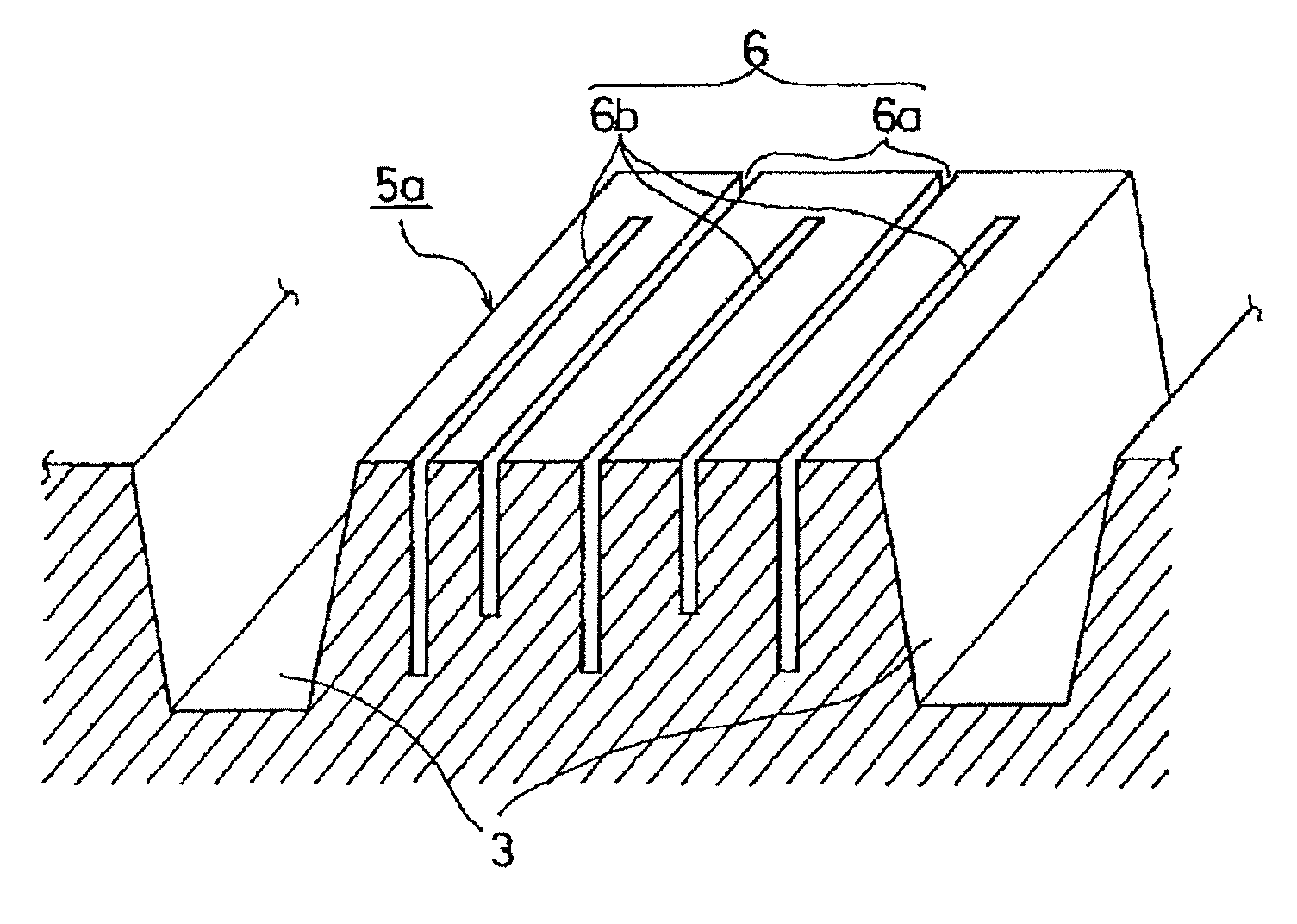
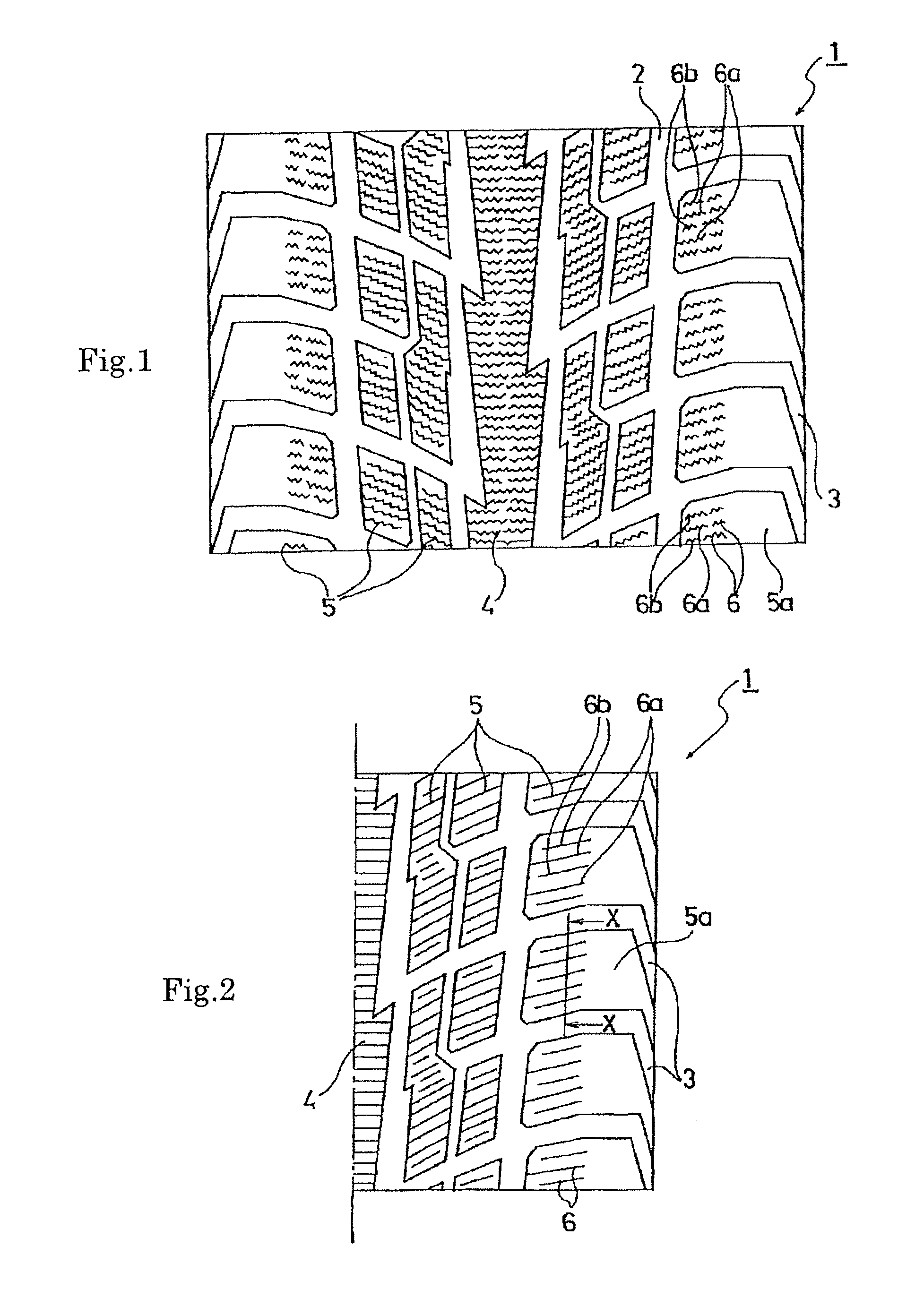
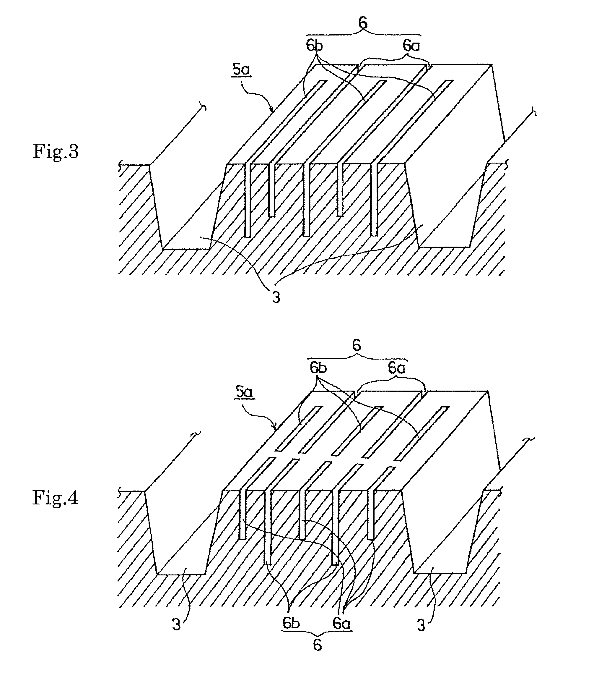
, sipe depths were uniform, all sipes were open sipes, the sipes were not divided, and each block was made of a single layer rubber composition alone. In Conventional Example 2, sipes were open sipes whose sipe depths were offset, but which were not divided, and each block was made of a single layer rubber composition alone. Example 1 is an example in which open sipes and closed sipes were alternately arranged, and the open sipes were offset so as to be shallower than the closed sipes, and corresponds to FIG. 3. Example 2 is a modified example of Example 1 where the sipes were divided, and corresponds to FIG. 4. Example 3 is a modified example of Example 2 where each block had a double layer structure, and a rubber composition having a higher rubber hardness was disposed in the lower layer side, and corresponds to FIG. 5.

[0034]These five kinds of tires were measured for on-ice braking, crack formation resistance, crack growth resistance by the following measurement methods, and were...


PUM


Abstract

A pneumatic tire has a tread surface for simultaneously achieving both enhanced on-ice performance and enhanced durability. The pneumatic tire includes sipes extending in the width direction of the tire that are arranged at intervals in the circumferential direction of the tire at least in shoulder blocks that are divided by longitudinal grooves extending in the circumferential direction of the tire and by lateral grooves extending in the width direction of the tire. Open sipes and closed sipes are alternately arranged, and the depth of the open sipes is less than the depth of the closed sipes.

Description

CROSS-REFERENCE TO RELATED APPLICATIONS[0001]This U.S. National stage application claims priority under 35 U.S.C. §119(a) to Japanese Patent Application No. 2008-235017, filed in Japan on Sept. 12, 2008, the entire contents of which are hereby incorporated herein by reference.TECHNICAL FIELD[0002]The present invention relates to a pneumatic tire, and more specifically to a pneumatic tire having a block row at least in a shoulder portion and multiple sipes which are provided in blocks of the block row and which extend in the width direction of the tire, the pneumatic tire having enhanced durability without impairing on-ice performance.BACKGROUND ART[0003]Generally, a block pattern is employed as the tread pattern of a winter tire (a studless tire). The block pattern enhances on-snow performance by facilitating biting of blocks into snow which is to be fitted into a space between blocks adjacent to each other in the circumferential direction of the tire. In addition, braking and drivi...

Claims


Application Information

Patent Timeline
Patent Type & Authority Patents(United States)
IPC IPC(8): B60C11/12B60C11/03
CPCB60C11/12B60C11/0302B60C11/0306B60C2011/1213B60C2011/0388B60C2011/1254B60C2011/1209B60C2011/1268Y10S152/03B60C11/005B60C2011/0025B60C11/03
Inventor YAMAKAWA, TAKAHIRO
Owner THE YOKOHAMA RUBBER CO LTD
Why Eureka
Try Eureka