Method of producing a recoil pad for a weapon

a recoil pad and weapon technology, applied in the field of producing a recoil pad for a weapon, can solve the problems of increasing the weight reducing the service life of the recoil pad,

Active Publication Date: 2014-08-26
HIVIZ LLC
View PDF10 Cites 6 Cited by
  • Summary
  • Abstract
  • Description
  • Claims
  • Application Information

AI Technical Summary

Problems solved by technology

Slip-on recoil pads typically do not provide a rigid base to affix the recoil pad to the target stock.
While there are a numerous and wide variety of conventional recoil pads in each of the above-described categories, there remain substantial unresolved problems.
One substantial problem with conventional recoil pads can be that the pad is a solid elastomer pad having a fixed homogeneous recoil pad structure and elastomer characteristics throughout the recoil pad.
A solid elastomer recoil pad in the first instance can add unwanted weight to the recoil pad.
Another substantial problem with conventional recoil pads can be that the number and structure of the air spaces internal to a particular recoil pad may be limited resulting in a corresponding limitation as to incremental variation within a graded series of recoil pads as to response in the absorption of recoil energy and response in delay transfer of recoil energy, or both in various permutations and combinations.
Another substantial problem with conventional recoil pads can be that the mold into which the elastomer may be molded to produce a conventional recoil pad may have an invariable mold structure that cannot be altered to provide a lesser or greater amount of air space as to particular regions or as to substantially the entirety of the internal recoil pad structure whether independent of or in relation to the external recoil pad structure or as to elastomer characteristics, or both, to correspondingly alter absorption of recoil energy or to delay transfer of recoil energy, or both in various permutations and combinations, from the target stock to the shooter.

Method used


Image

  • Method of producing a recoil pad for a weapon
  • Method of producing a recoil pad for a weapon
  • Method of producing a recoil pad for a weapon

Examples


Embodiment Construction

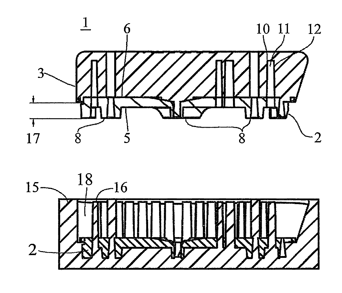
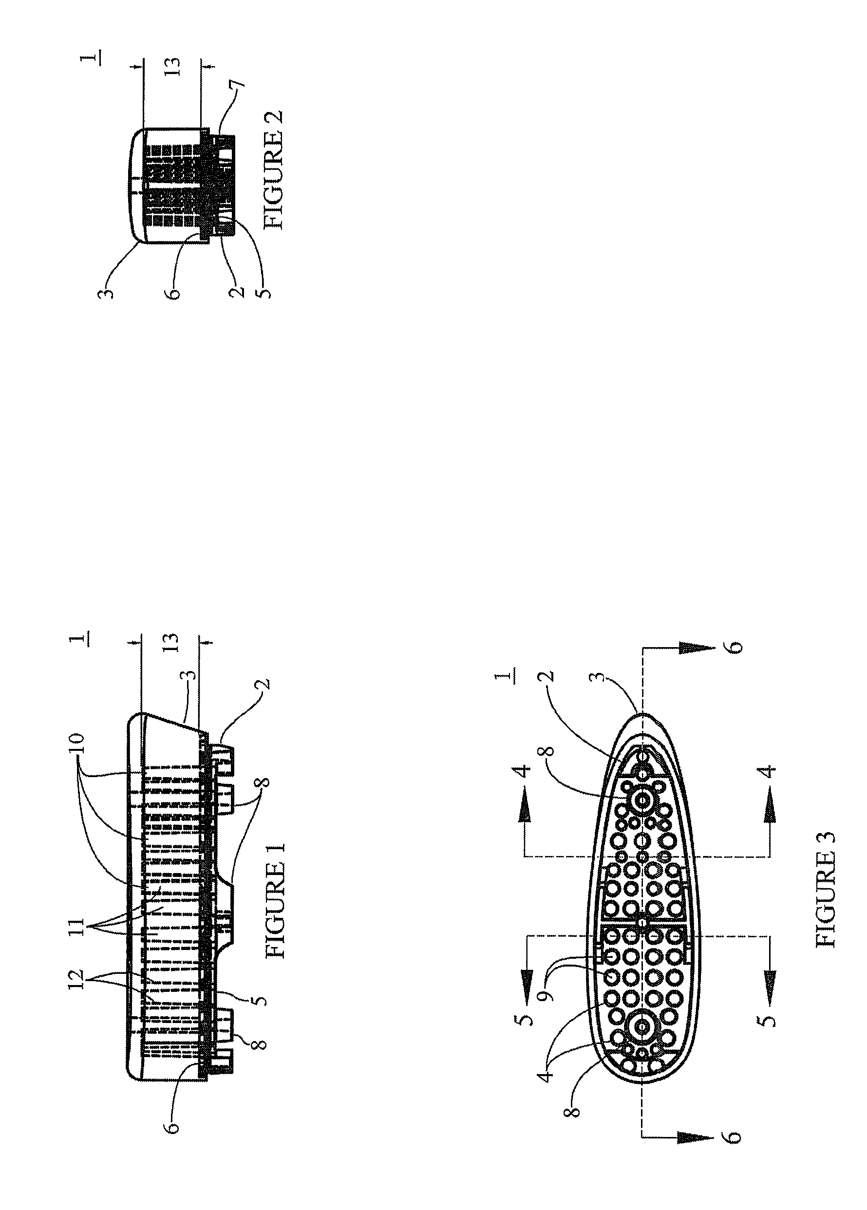
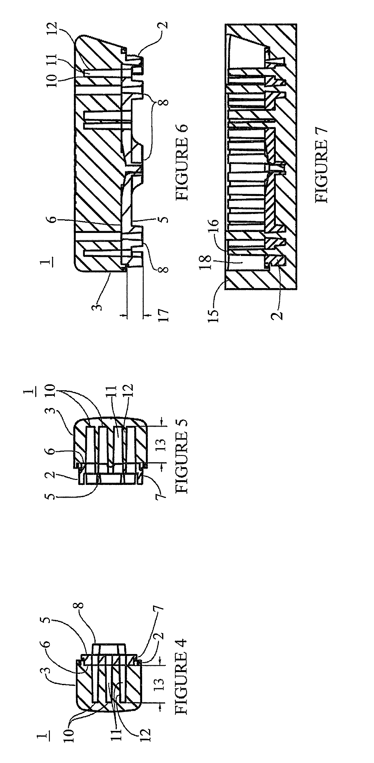
[0035]Now referring primarily to FIGS. 1-6, which show a pre-fit embodiment of the inventive recoil pad (1) which includes an inventive base (2) and an inventive pad (3). The base (2) can be formed, molded, fabricated or the like from a variety of materials having sufficient strength to be joined to a target stock (by adhesive, mechanical fasteners, or otherwise) and used for the purpose of supporting an over-mold pad (3) during use of a weapon. Typically, the weapon will be a rifle or shotgun; however, the invention is not so limited, and the inventive pre-fit recoil pad or other recoil pads described herein can be used to absorb recoil energy or delay transfer of recoil energy, or both, in various relations depending upon the recoil pad structure and the elastomer characteristics, from any type of weapon regardless of the use, such as military weapons, sport weapons, or the like.

[0036]Typically, the base (2) will be produced from a plastic material using injection molding techniqu...


PUM

PropertyMeasurementUnit
specific gravityaaaaaaaaaa
tensile strengthaaaaaaaaaa

Abstract

A recoil pad having a pad in which the elastomer contains a plurality of pockets having one or more pocket characteristics adjustable over the entirety or portions of the pad to achieve recoil pad characteristics which can be incrementally variably matched to the recoil energy characteristics and recoil energy transfer characteristics of a particular target stock.

Description

[0001]This United States Non-Provisional Patent Application claims the benefit of U.S. Provisional Patent Application No. 61 / 460,338, filed Dec. 31, 2010, hereby incorporated by reference herein.I. FIELD OF THE INVENTION[0002]A recoil pad having a pad in which the elastomer contains a plurality of pockets having one or more pocket characteristics adjustable over the entirety or portions of the pad to achieve recoil pad characteristics which can be incrementally variably matched to the recoil energy characteristics and recoil energy transfer characteristics of a particular target stock.II. BACKGROUND OF THE INVENTION[0003]Conventional recoil pads generally fall into three categories.[0004]Pre-fit recoil pads generally provide a rigid base coupled to an elastomer pad. The rigid base has a configuration which mates to a particular configuration of synthetic target stock. For each different configuration of synthetic target stock there can be a correspondingly differently configured rig...

Claims


Application Information

Patent Timeline
Patent Type & Authority Patents(United States)
IPC IPC(8): B29C39/10
CPCB29C33/42F41C23/08B29C33/308B29C33/306
Inventor HOWE, PHILLIP D.MOORE, RICHARD A.HERNDON, RICHARD K.
Owner HIVIZ LLC
Why Eureka
Try Eureka