
Methods and systems for mitigating distortion of gas turbine shaft

a technology of gas turbine engine and shaft, which is applied in the direction of engine starter, turbine/propulsion engine ignition, machine/engine, etc., can solve the problems of shaft being distorted, cooling unevenly, and the top of the shaft in the turbine being hotter, so as to achieve the effect of reducing the distortion of the sha

Active Publication Date: 2014-09-02
GENERAL ELECTRIC CO
View PDF21 Cites 71 Cited by
  • Summary
  • Abstract
  • Description
  • Claims
  • Application Information

AI Technical Summary

Benefits of technology

The present invention relates to methods and systems for mitigating distortion of a shaft in a gas turbine engine. The technical effects include reducing shaft distortion, improving engine starting, and enhancing operational efficiency. Specifically, the methods involve applying intermittent rotary power to the shaft during conditions where temperature differences can cause distortion, and stopping the application of rotary power when the engine is started. The systems include sensors, an auxiliary rotary power supply, and a controller that applies pulse signals to the auxiliary rotary power supply to control the application of intermittent rotary power.

Problems solved by technology

It has been generally observed that certain gas turbine engines, e.g. aircraft turbofan engines, cool unevenly following shutdown of the engine.
It has been further observed that this uneven cooling may cause a top of a shaft in the turbine being hotter than the bottom of the shaft.
Owing to thermal expansion of the material, the net result of this temperature differential can often be that the shaft becomes distorted, where typically this distortion is in the form of a “bowing” (sometimes referred to as “hogging”), usually upwardly, of the shaft.
This distortion may become problematic if a start is attempted with an aviation gas turbine engine in this condition.
In such instances, the shaft eccentricity will result in vibrations which may be felt in the airplane, or may result in rubbing of a rotor blade or fan blade so as to negatively affect performance of the turbine.
This may, in itself, require the expenditure of a considerable amount of power and has other potentially undesirable effects.
However, such extended motoring may be undesirable owing to the consumption of power.
Furthermore, such extended motoring typically lengthens the start time, and undesirable bowed-rotor vibration may be encountered during the motoring.
This may be especially problematic in some newer turbofan engines.

Method used


Image

  • Methods and systems for mitigating distortion of gas turbine shaft
  • Methods and systems for mitigating distortion of gas turbine shaft
  • Methods and systems for mitigating distortion of gas turbine shaft

Examples


example

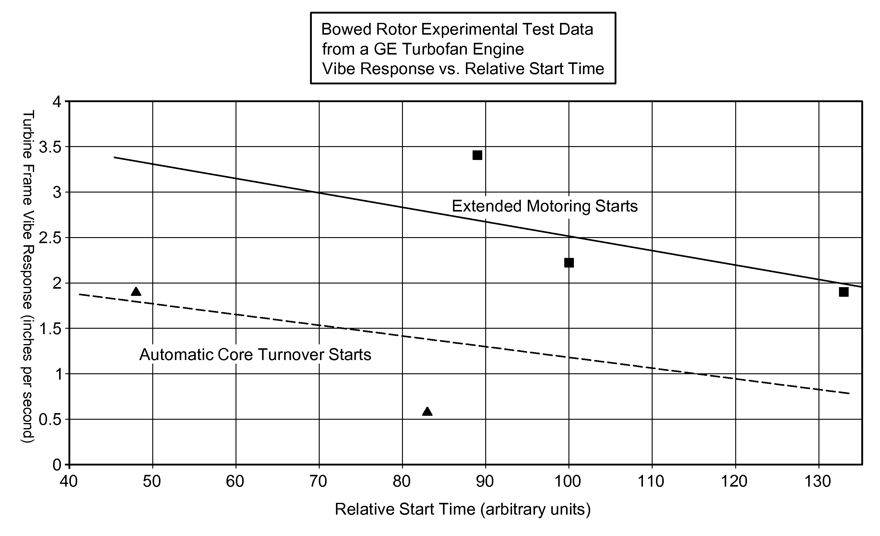
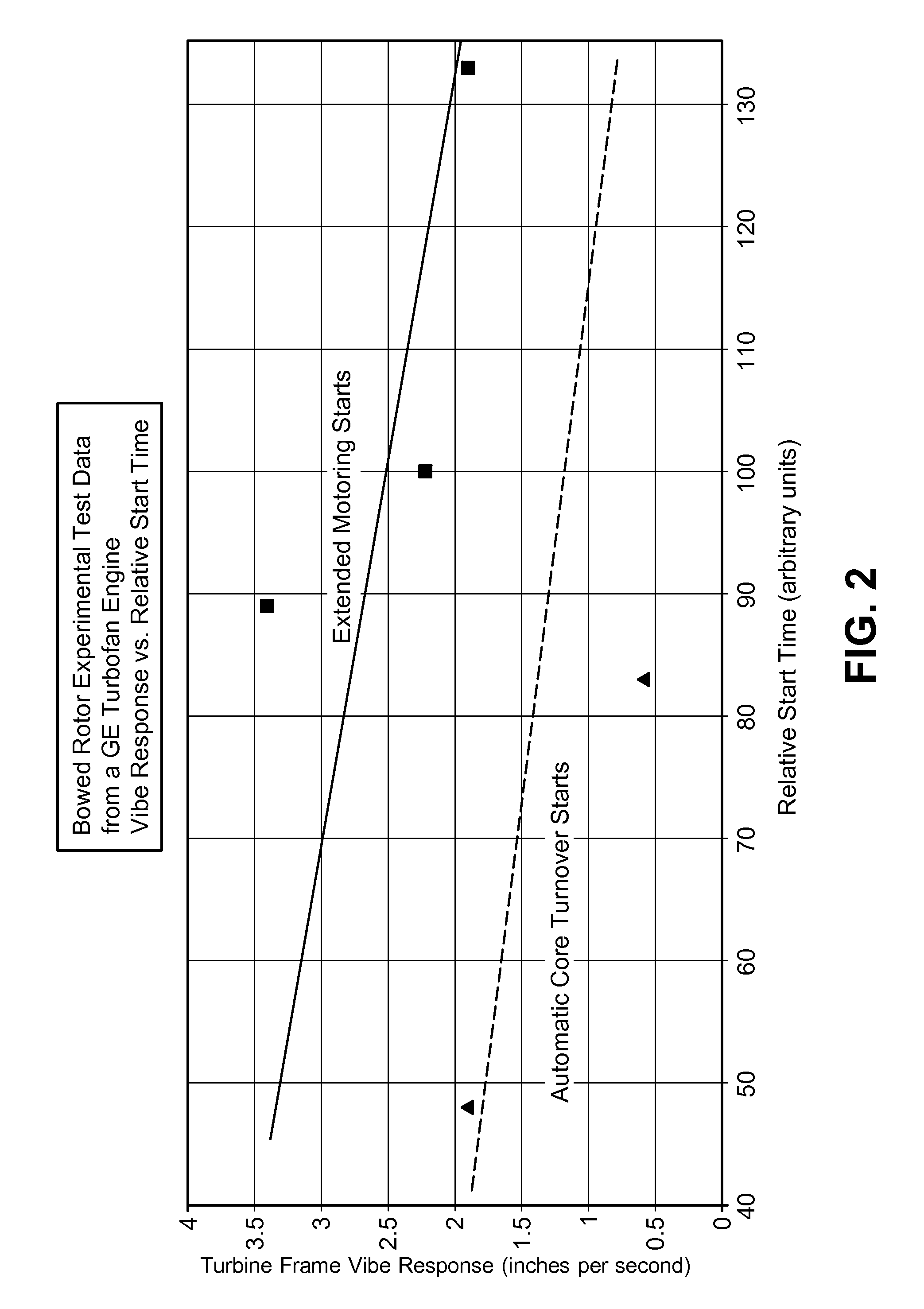
[0034]A test was performed on a GEnx-1B type turbofan engine (GEnx is a trademark of General Electric Company). Vibrations (“vibes”) were measured as a function of relative start time, i.e., time after start of engine (in arbitrary time units). Vibrations were measured in terms of ips units (inches per second), generally a measure of peak amplitude of the vibration.

[0035]The top graph (i.e., solid line) of FIG. 2 refers to a procedure where extended motoring time was performed on the engine during the start procedure prior to fuel on. This extended motoring was conducted in such a manner that airflow through the engine core evened out the temperature disparity between the top and bottom of the rotor. Vibrations were measured as a function of start time. However, the extended motoring was seen to lengthen the start time, as compared to the application of intermittent rotary power in accordance with embodiments of the invention. By following the procedures of the present disclosure (r...


PUM


Abstract

Methods and systems for mitigating distortion of a shaft of a gas turbine engine are provided. One method comprises at least one step of applying intermittent rotary power to a shaft of a gas turbine engine. The step of applying intermittent power to the shaft is performed during a period where conditions of temperature differential in the engine exist capable of distorting the shaft. The methods and systems shorten the time needed to start a gas turbine engine in such a way that bowing of a shaft is not a significant problem.

Description

CROSS REFERENCE TO RELATED APPLICATIONS[0001]This application is a non-provisional utility application claiming priority under 35 U.S.C. 119(e) of prior-filed provisional application Ser. No. 61 / 248,554, filed 5 Oct. 2009, entitled “METHODS AND SYSTEMS FOR MITIGATING DISTORTION OF GAS TURBINE SHAFT”, which is hereby incorporated by reference in its entirety.FIELD OF THE INVENTION[0002]The present invention generally relates to methods and systems for mitigating distortion of a shaft of a gas turbine engine. In particular, some embodiments herein relate to methods and systems for mitigating bowing of a high pressure shaft of a turbofan engine.BACKGROUND[0003]It has been generally observed that certain gas turbine engines, e.g. aircraft turbofan engines, cool unevenly following shutdown of the engine. Typically, it has been observed that the top of the engine may remain remaining hotter than the bottom of the engine for a period of time after shutdown. Because of convection effects th...

Claims


Application Information

Patent Timeline
Patent Type & Authority Patents(United States)
IPC IPC(8): F02C9/00F01K13/00F02C7/26
CPCF02C7/26F05D2270/114F01D25/34F05D2260/85
Inventor ROSS, STEVEN A.AGIN, THOMAS E.
Owner GENERAL ELECTRIC CO
Learn More