
Sensored pick assembly

Active Publication Date: 2014-09-02
SCHLUMBERGER TECH CORP
View PDF18 Cites 20 Cited by
  • Summary
  • Abstract
  • Description
  • Claims
  • Application Information

AI Technical Summary

Benefits of technology

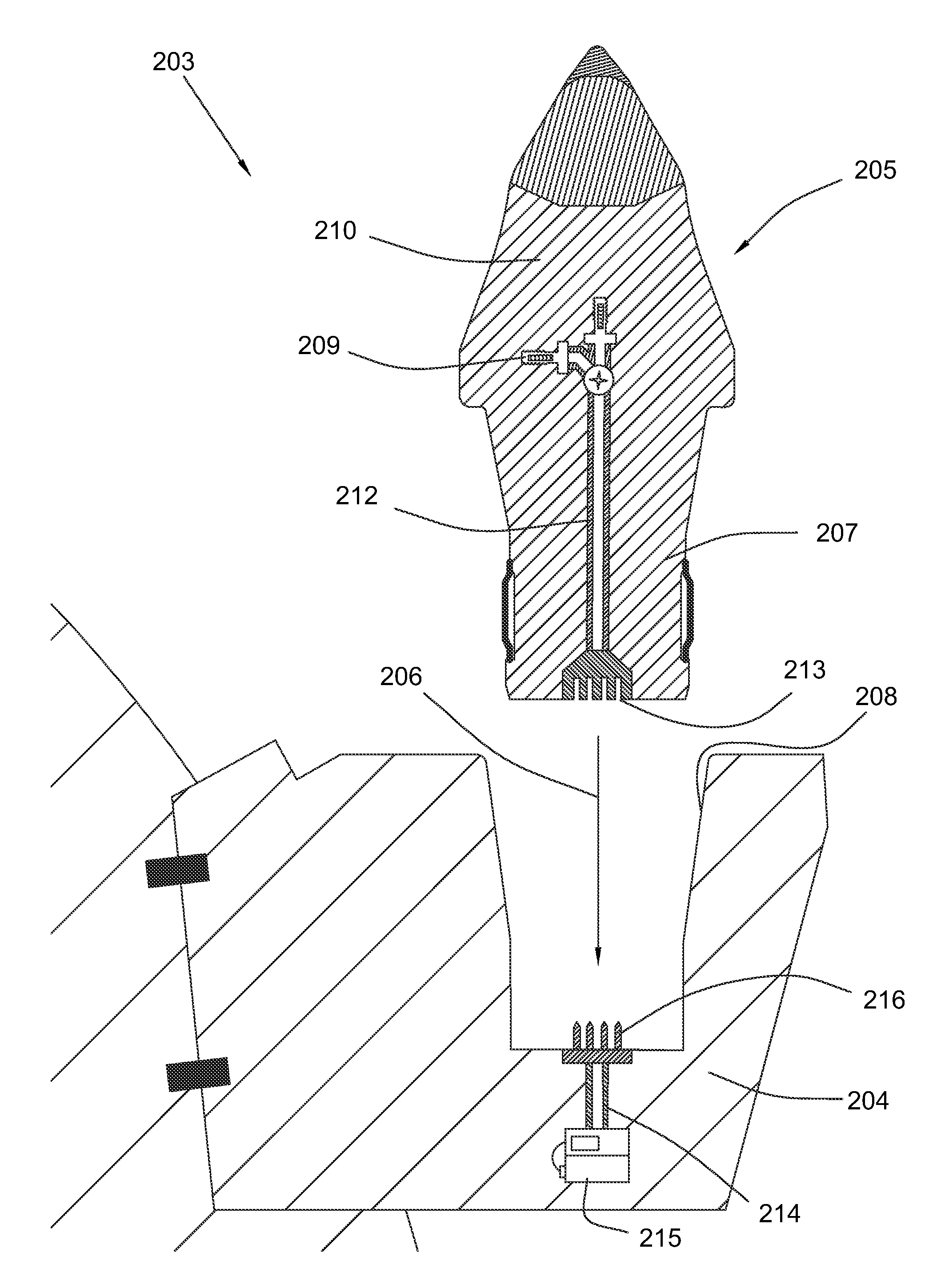
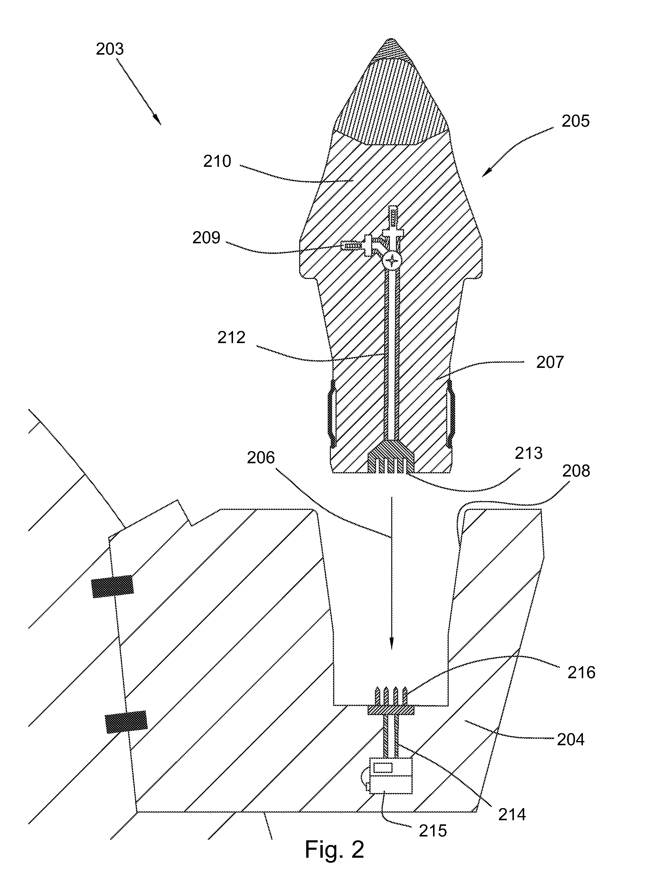
The present invention provides a degradation assembly for use in a drilling tool. The assembly includes a pick with a sensor mounted on it, a first conductor in communication with the sensor, and a receiving element with a second conductor. The pick can be inserted into the receiving element through a stab connector or an inductive coupling, and the connection can be releasable. The receiving element can support the pick at an angle of attack and includes a complementary surface that matches the surface of the pick shank. The sensors can be strain gauges, accelerometers, thermocouples, or magnetometers, and some sensors can be powered by an external power source. The pick also includes a frustoconical bolster, a conical degradation tip, and a polycrystalline diamond material. The technical effects include improved sensory feedback and reduced wear on the pick during drilling operations.

Problems solved by technology

However, as sensors are disposed closer to the point of degradation, it may become necessary to quickly replace a sensor at the same time worn cutters are replaced.

Method used


Image

  • Sensored pick assembly
  • Sensored pick assembly
  • Sensored pick assembly

Examples


Embodiment Construction

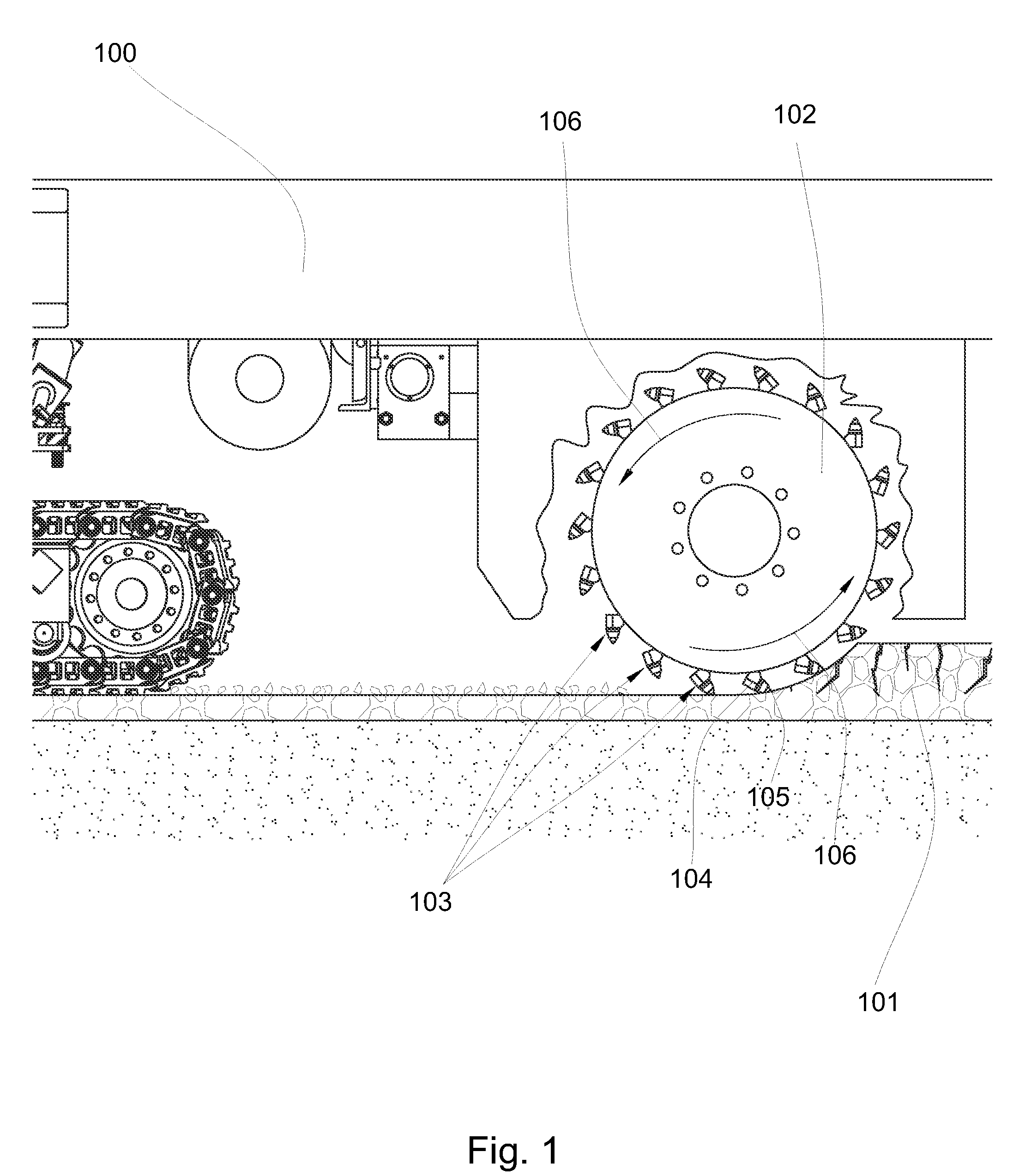
[0016]Referring now to the figures, FIG. 1 discloses an embodiment of a rotary degradation machine in the form of a road milling machine 100. The road milling machine 100 also known as a cold planer, may be used to degrade a formation 101 such as pavement, concrete, or asphalt prior to placement of a new layer. Other types of rotary degradation machines may include mining, trenching or drilling machines that may degrade both natural and manmade formations. The road milling machine 100 may comprise a driving mechanism such as a rotary degradation drum 102. The rotary degradation drum 102 may comprise a plurality of pick assemblies 103 secured to its outer surface. Each of the pick assemblies 103 may comprise a receiving element 104 including a bore with a pick 105 secured within the bore of the receiving element 104. During normal operation, the degradation drum 102 may rotate in a direction indicated by arrows 106, causing the pick 105 to engage and degrade the formation 101. In oth...


PUM


Abstract

A degradation assembly may comprise at least one sensor mounted on a pick; the pick comprising a first conductor in communication with the sensor. The assembly may also comprise a receiving element including a bore comprising a second conductor. The first and second conductors may combine to create a connection as the pick is inserted into the bore of the receiving element.

Description

BACKGROUND OF THE INVENTION[0001]Degradation assemblies may be used in mining, trenching, and road milling operations to degrade natural and man-made formations. The present invention relates to degradation assemblies and especially to degradation assemblies comprising sensors. The following references disclose degradation assemblies comprising sensors that measure various occurrences during a degradation process.[0002]U.S. Pat. No. 2,741,468 to Alspaugh, discloses a thermocouple mounted in an outer tooth of a boring machine. The thermocouple is electrically connected to a remote control point and thereby conveys temperature readings to a meter at that point. Electrical connections from the thermocouple are carried through an arm assembly to slip rings by means of cable.[0003]U.S. Pat. No. 4,181,360 to Wilson, discloses a mineral mining machine comprising a rotary cutter head with a sensor to detect a cutting horizon of the cutter head relative to a boundary of a mineral seam and to...

Claims


Application Information

Patent Timeline
Patent Type & Authority Patents(United States)
IPC IPC(8): E21C39/00
CPCE21C39/00E21C2035/1813E21C35/183E21C35/18E21C35/1835
Inventor HALL, DAVID, R.
Owner SCHLUMBERGER TECH CORP
Learn More