Anchor device

Active Publication Date: 2014-09-02
KASSEL BLAKE
View PDF16 Cites 37 Cited by
  • Summary
  • Abstract
  • Description
  • Claims
  • Application Information

AI Technical Summary

Benefits of technology

[0019]In a preferred embodiment, loop members of the anchor device include an outer, strong, fabric member and an inner member attached to said fabric member and having a lower coefficient of friction than said fabric member to minimize wear of an elastic

Problems solved by technology

In applicant's opinion, the anchor device disclosed in Montesquieux does not have the desired reliability and versatility achieved by applicant's anchor device.
An anchor device of the type disclosed in the Rotella '483 patent has limited capabilities; that is, it is not well designed for providing the desire

Method used


Image

  • Anchor device
  • Anchor device
  • Anchor device

Examples


Example

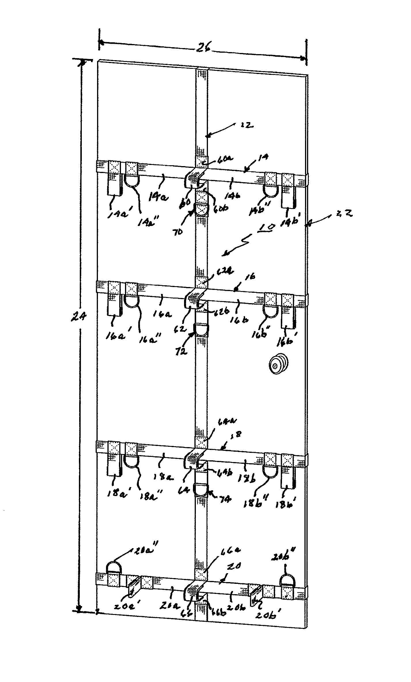
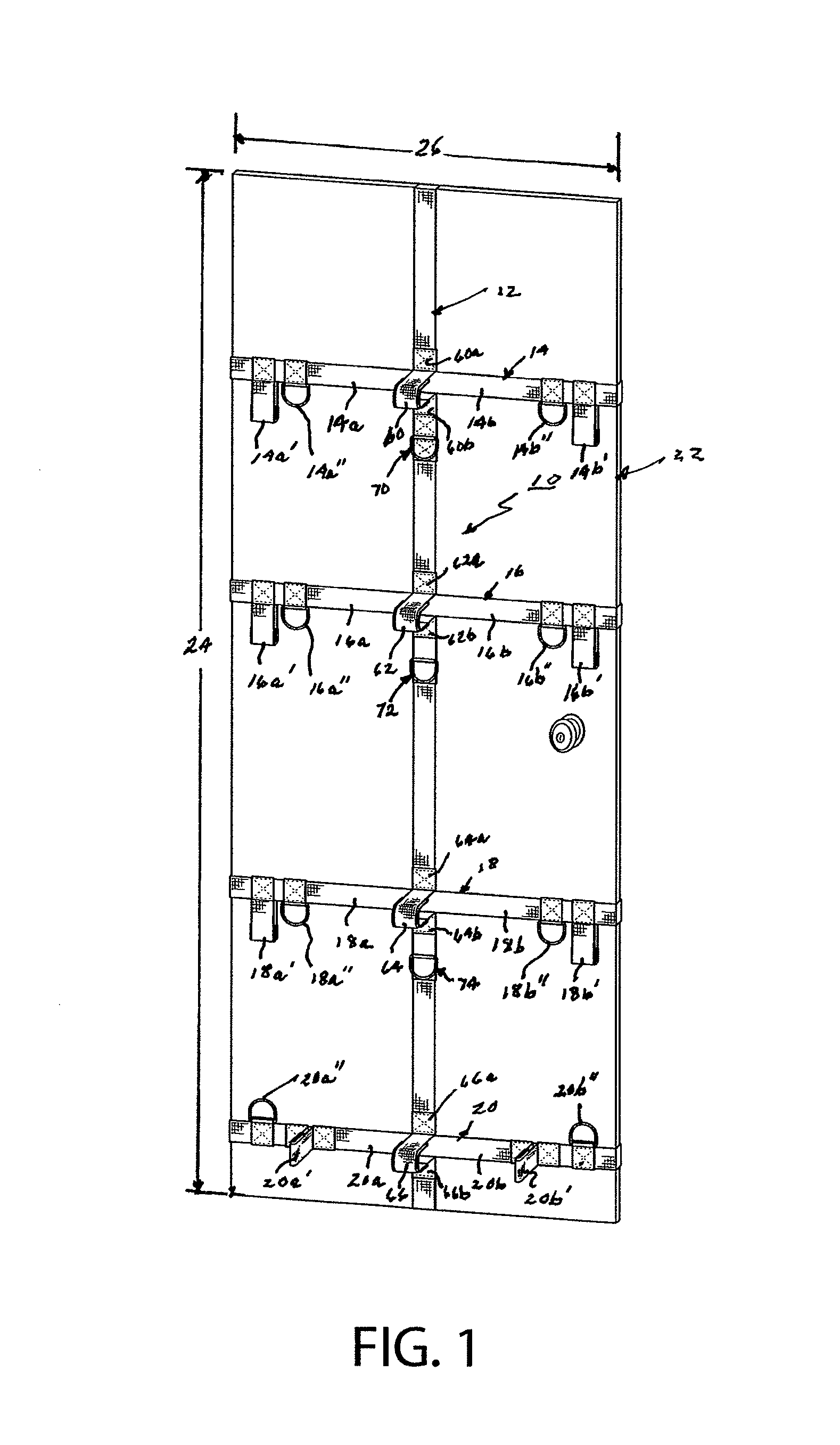
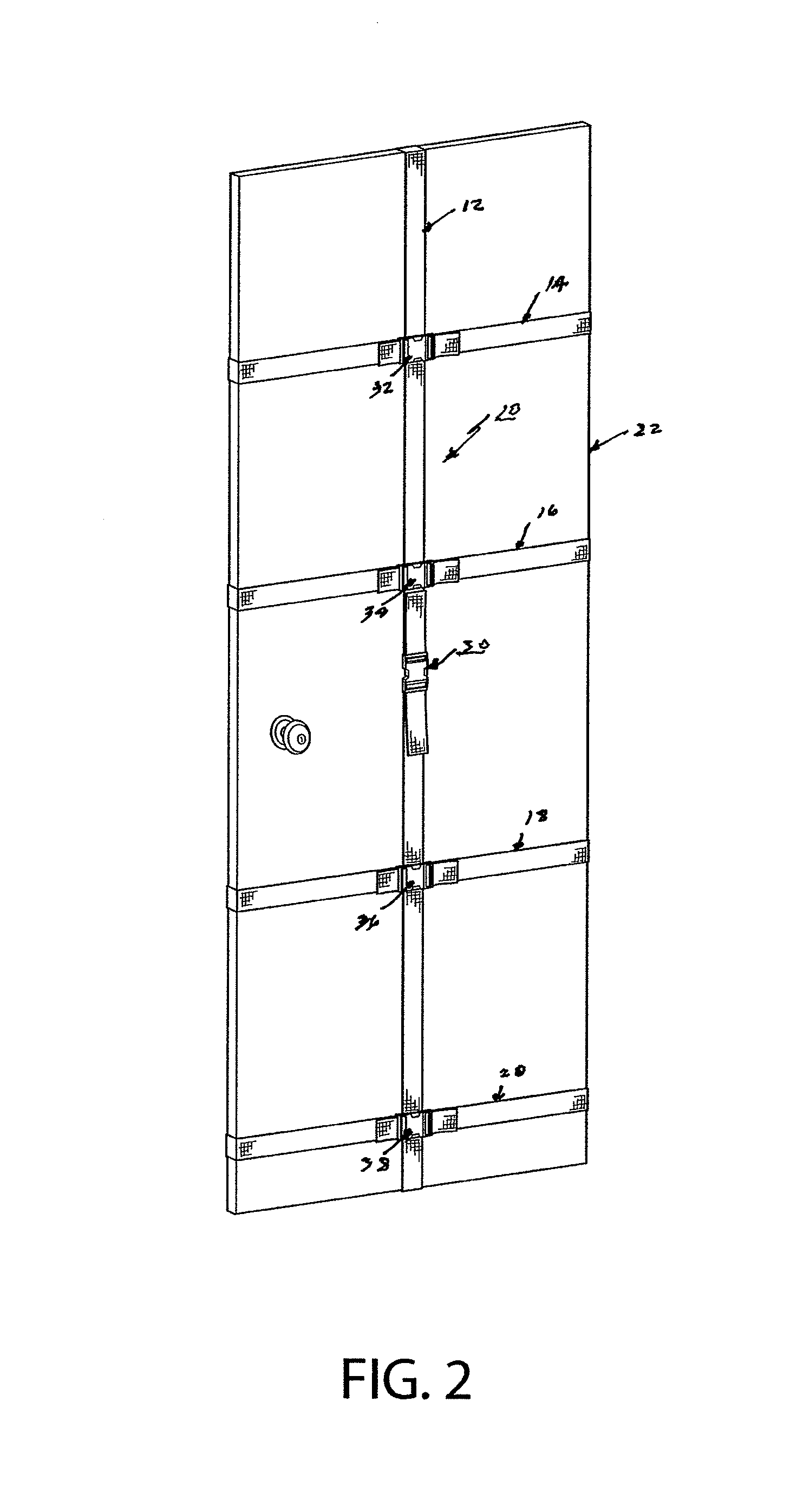
[0035]Referring to FIGS. 1 and 2, an anchor device in accordance with this invention is illustrated generally at 10. This anchor device includes a vertically oriented strap member 12 and a plurality of horizontal strap members 14, 16, 18 and 20, mounted or connected to the vertically oriented strap member 12 in vertically spaced apart relationship to each other. It should be understood that the number of horizontal strap members employed in the anchor device is a matter of choice; however, in the preferred embodiment of this invention at least two such horizontal strap members are employed and most preferably four such horizontal strap members are employed. However, in accordance with the broadest aspects of this invention a single horizontal strap member can be employed; having the construction and arrangement of elements of any one of the horizontal strap members 14, 16, 18 and 20, to be described in detail later herein.

[0036]Reference throughout this application to a “plurality” ...


PUM


Abstract

An anchor device for elastic exercise bands mountable on a vertical support member (e.g., a door) and includes a vertically oriented strap member and a plurality of horizontal strap members attached to a front section of the vertically oriented strap member in vertically spaced relationship to each other. At least two, transversely spaced-apart loop members for receiving an elastic exercise band therethrough are attached to at least one of the plurality of horizontal strap members. At least two, transversely spaced-apart ring members are attached to at least one of the plurality of horizontal strap members for receiving one or more elastic exercise bands.

Description

BACKGROUND OF THE INVENTION[0001]1. Field of Invention[0002]This invention relates generally to an anchor device and more specifically to a multi-functional anchor device designed for use with elastic exercise bands.[0003]2. Description of Related Art[0004]Resistance training is an extremely popular form of exercise, employing a variety of different devices. One very popular resistance training device employs stretchable tubes or bands having handles or other body securement means attached to one or both of the opposed ends thereof, either directly or through attachment straps, carabineers and the like.[0005]In order to enhance the versatility of training with elastic bands a variety of different anchor devices have been disclosed in the prior art. These anchor devices have been designed to be attached to various supporting surfaces, such as vertical walls, doors, mattresses and the like. For example, note the anchor devices disclosed in the following patents and publications: U.S. ...

Claims


Application Information

Patent Timeline
IPC IPC(8): A63B21/00
CPCA63B21/00A63B21/0442A63B23/035A63B21/1645A63B23/1281A63B21/1469A63B23/1263A63B23/1254A63B21/1484A63B21/068A63B21/0557A63B21/00065A63B21/4035A63B21/4043
Inventor KASSEL, BLAKE
Owner KASSEL BLAKE
Why Eureka
Try Eureka