Steering apparatus

a technology of steering apparatus and operating lever, which is applied in the direction of steering column, steering parts, vehicle components, etc., can solve the problems of poor fastening ability and complicated initial setting, and achieve favorable operation feeling, reduce the operating load of the operating lever, and facilitate the operation of unlocking operation.

Inactive Publication Date: 2014-09-09
YAMADA MANUFACTURING CO LTD
View PDF5 Cites 14 Cited by
  • Summary
  • Abstract
  • Description
  • Claims
  • Application Information

AI Technical Summary

Benefits of technology

[0010]Furthermore, in a case where the connecting rod 50 and the first stopper 51 are fastened using a screwing method by rotating the second stopper 52, it is difficult to fix the rotating second stopper 52 in the guide slot 33 of the fixed bracket 32. Hence, positioning during fastening is difficult in both cases, and therefore a fastening ability is poor. An object of (a technical problem to be solved by) the present invention is to improve the operation feeling of locking and unlocking operations during tilt and telescopic adjustment, and to improve the fastening ability of an apparatus.
[0013]In the first aspect of the present invention, a lock mechanism is constituted by the main driving cam, the driven cam, and the intermediate cam, and the intermediate cam is provided between the main driving cam and the driven cam. Further, axial direction separation and approach operations between the main driving cam and the intermediate cam and axial direction separation and approach operations between the intermediate cam and the driven cam can be performed in two-stage rotation operations. Due to this two-stage operation, lift amounts generated during separation can be divided into smaller amounts, and therefore an operating load of the operating lever can be reduced during both locking and unlocking. As a result, a favorable operation feeling can be obtained in the operating lever. Further, the operating lever can be prevented from returning too rapidly during unlocking, and therefore an unlocking operation can be performed favorably.
[0014]In the second aspect of the present invention, the separation distance between the main driving cam and the intermediate cam is made equal to the separation distance between the driven cam and the intermediate cam. Therefore, the main driving cam and driven cam can be formed with identical shapes and the respective axial direction side faces of the intermediate cam can be formed with identical cam surface shapes, enabling a reduction in manufacturing cost and easy assembly.
[0015]In the third aspect of the present invention, the separation distance between the main driving cam and the intermediate cam is made different to the separation distance between the driven cam and the intermediate cam. In so doing, the lift amount can be increased without impairing the operating feeling during locking and unlocking.

Problems solved by technology

Therefore, initial setting is complicated.
Hence, positioning during fastening is difficult in both cases, and therefore a fastening ability is poor.

Method used


Image

  • Steering apparatus
  • Steering apparatus
  • Steering apparatus

Examples


first embodiment

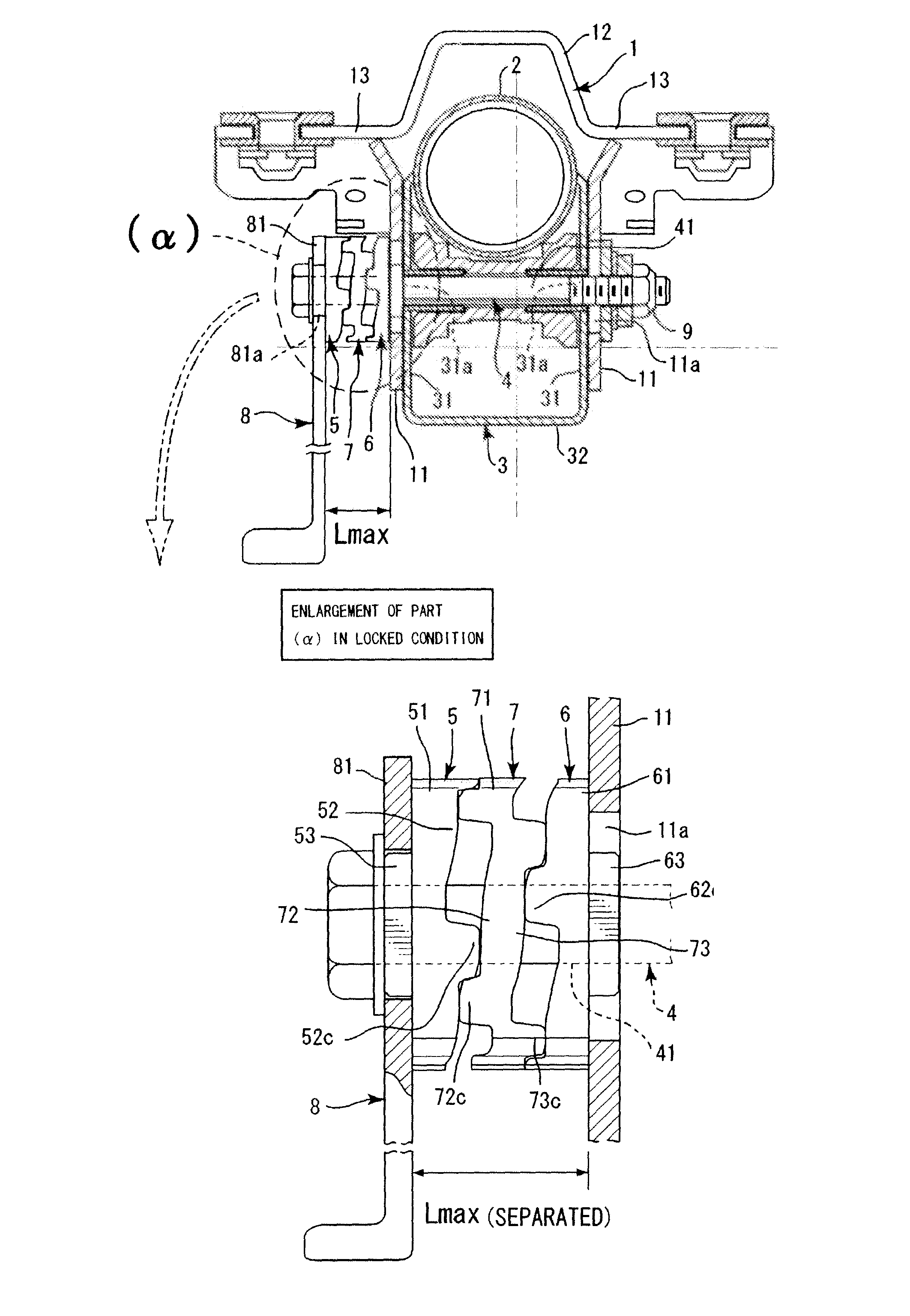
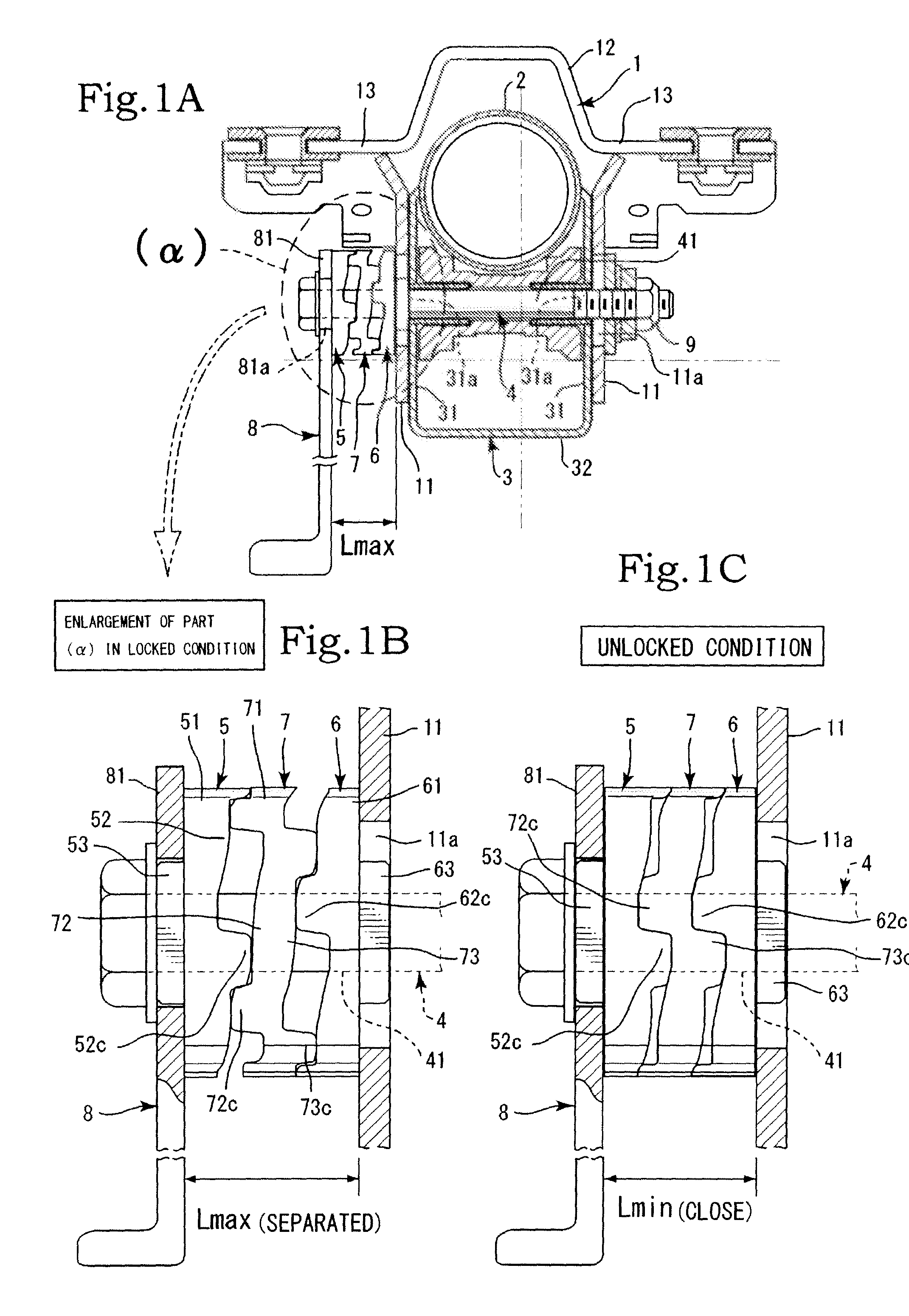
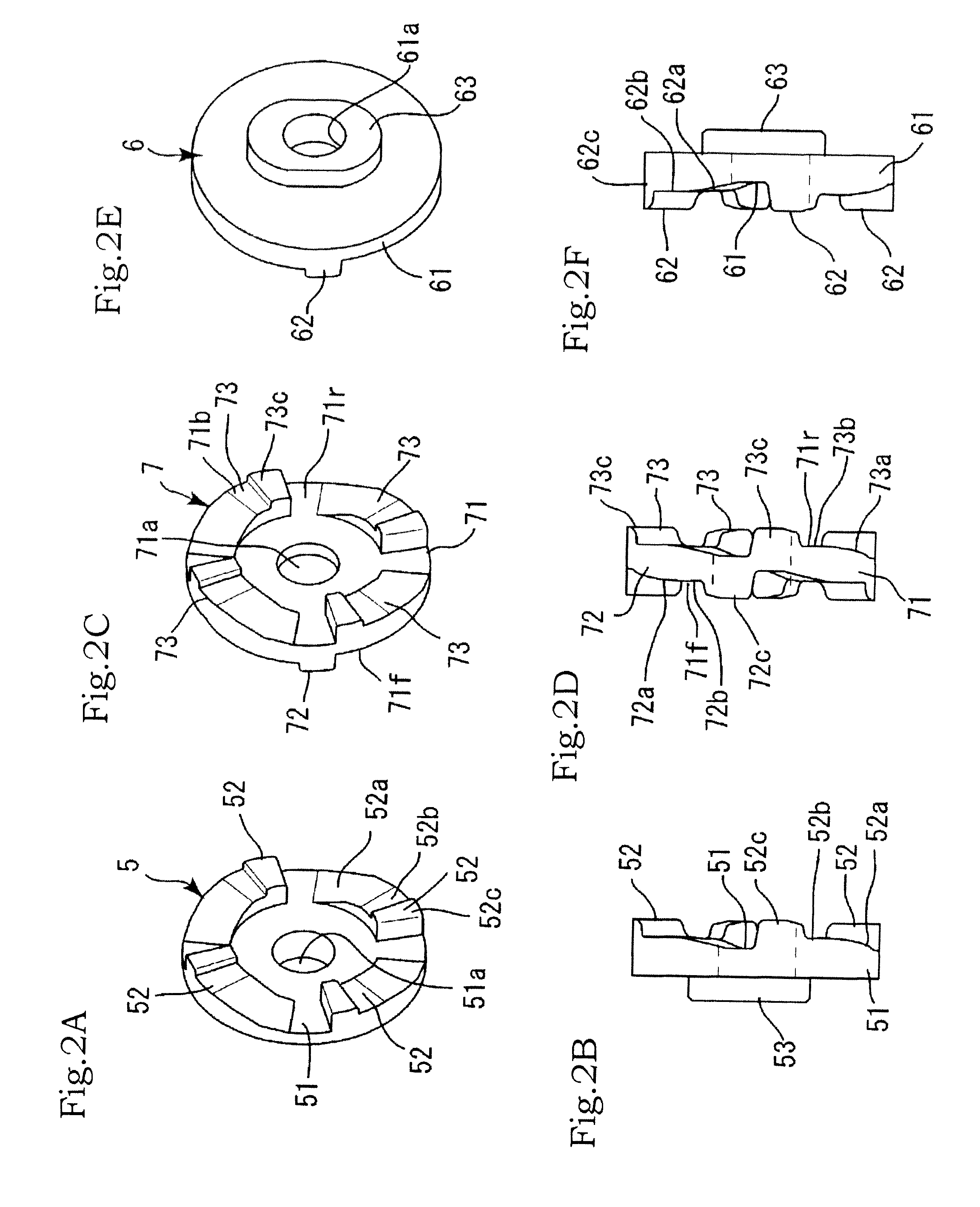
[0027]Next, the main driving cam 5, the driven cam 6, and the intermediate cam 7 will be described. A plurality of embodiments exists with regard to the constitutions of the cams. In a first embodiment, the main driving cam 5 is formed from a cam base portion 51 and a plurality of cam operating portions 52 (see FIG. 1 and FIGS. 2A and 2B). The cam base portion 51 is formed substantially in a disc shape, and an attachment hole 51a is formed in a center of the cam base portion 51.

[0028]The attachment hole 51a is press-fitted to a press-fitting region of the lock bolt 4 such that the main driving cam 5 is capable of rotating in a periaxial direction of the lock bolt 4 together therewith. The plurality of cam operating portions 52 are formed in a circumferential direction in an appropriate region on an outer periphery of one side face of the cam base portion 51 (see FIGS. 2A and 2B).

[0029]An inclined surface 52a, a top surface 52b, and a cam projecting portion 52c are formed continuousl...

second embodiment

[0053]In a second embodiment, on the other hand, the cam operating portions 52 of the main driving cam 5 are shaped differently to the cam operating portions 62 of the driven cam 6 such that the separation distance between the main driving cam 5 and the intermediate cam 7 is different to the separation distance between the driven cam 6 and the intermediate cam 7. In this embodiment, a height Ha from the cam surface of the cam base portion 51 of the main driving cam 5 to the top surface 52b of the cam operating portion 52 is different to a height Hb from the cam surface of the cam base portion 61 of the driven cam 6 to the top surface 62b of the cam operating portion 62.

[0054]In an embodiment shown in FIG. 5, the height Ha from the cam surface to the top surface 52b of the cam operating portion 52 is greater than the height Hb from the cam surface of the cam base portion 61 of the driven cam 6 to the top surface 62b of the cam operating portion 62, and therefore Ha>Hb. Accordingly, a...


PUM


Abstract

A steering apparatus exhibits favorable lever operability and generates a powerful steering column fastening and fixing force during tilt and telescopic adjustment. It has a simple structure includes: a column supporting member; a fixed bracket having, fixed side portions; a lock bolt that penetrates the respective fixed side portions of the fixed bracket together with the column supporting member; a main driving cam; a driven cam; an intermediate cam; and an operating lever. The lock bolt penetrates the main driving cam, the driven cam, and the intermediate cam, the main driving cam is rotated by the operating lever, the driven cam is attached to the fixed side portions to be incapable of rotating, the intermediate cam is disposed between the main driving cam and the driven cam, and the intermediate cam is caused to approach and separate from the main driving cam and the driven cam.

Description

BACKGROUND OF THE INVENTION[0001]1. Field of the Invention[0002]The present invention relates to a steering apparatus that exhibits favorable lever operability and generates a powerful steering column fastening and fixing force during tilt and telescopic adjustment while having an extremely simple structure.[0003]2. Description of the Related Art[0004]A conventional steering apparatus having a tilt and telescopic adjustment function includes a lock mechanism with which locking is achieved by rotating a spindle that penetrates a side plate of a fixed bracket fixed to a vehicle using an operating lever so as to press the side plate of the fixed bracket. Japanese Patent Application Publication No 2004-210265 is available as this type of steering apparatus.[0005]To summarize the content of Japanese Patent Application Publication No. 2004-210265 (reference symbols provided in the description of Japanese Patent Application Publication No. 2004-210265 are used as is), a connecting rod 50 i...

Claims


Application Information

Patent Timeline
Patent Type & Authority Patents(United States)
IPC IPC(8): B62D1/16B62D1/18B62D1/184
CPCB62D1/184
Inventor MANIWA, TAKAHIRO
Owner YAMADA MANUFACTURING CO LTD
Why Eureka
Try Eureka