
Variable intake system for vehicle, and apparatus and method for controlling the same

a variable intake and vehicle technology, applied in the direction of air intakes for fuel, combustion-air/fuel-air treatment, machines/engines, etc., can solve the problems of increasing manufacturing costs, reducing the linearity of acceleration, and retarding response speed, so as to improve engine performance, optimize noise reduction, and minimize the loss of intake pressure

Active Publication Date: 2014-09-09
HYUNDAI MOTOR CO LTD +1
View PDF11 Cites 11 Cited by
  • Summary
  • Abstract
  • Description
  • Claims
  • Application Information

AI Technical Summary

Benefits of technology

The present invention allows for quick and accurate control of a variable intake valve based on engine operating conditions to achieve better performance. It uses a linear motor actuator and optimizes air intake to minimize loss of pressure and reduce noise. Compared to existing active types, the present invention is cost-effective and achieves better engine performance with quicker and more precise control of the intake valve.

Problems solved by technology

However, the semi-active actuator according to the related art cannot easily adjust an opening area of an intake duct, cannot be fully opened at a maximum RPM of an engine, causing a loss of maximum output due to an increase of intake pressure, may degrade the linearity in acceleration booming, and may retard response speed, which is undesirable.
Further, while the active actuator according to the related art can be variably opened according to a mode thereof and can achieve quick response, it increases manufacturing costs, makes a power transmitting part complex, generates noise at a choking part and the like, and makes a prompt and accurate control difficult as it employs an high-priced DC motor as compared with a semi-active actuator, which is also undesirable.

Method used


Image

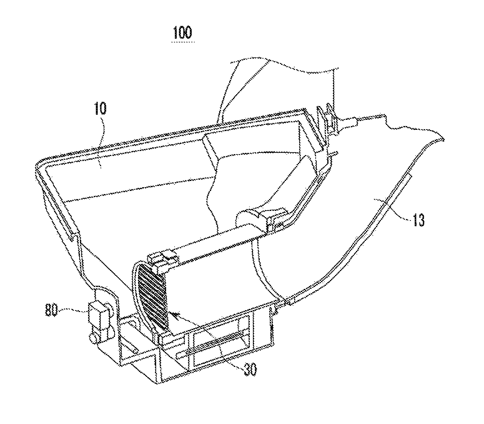
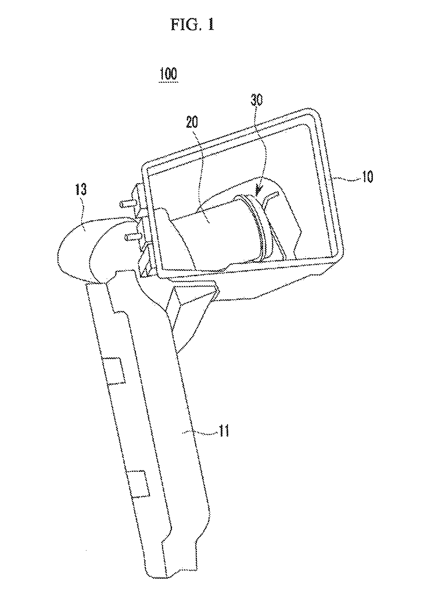
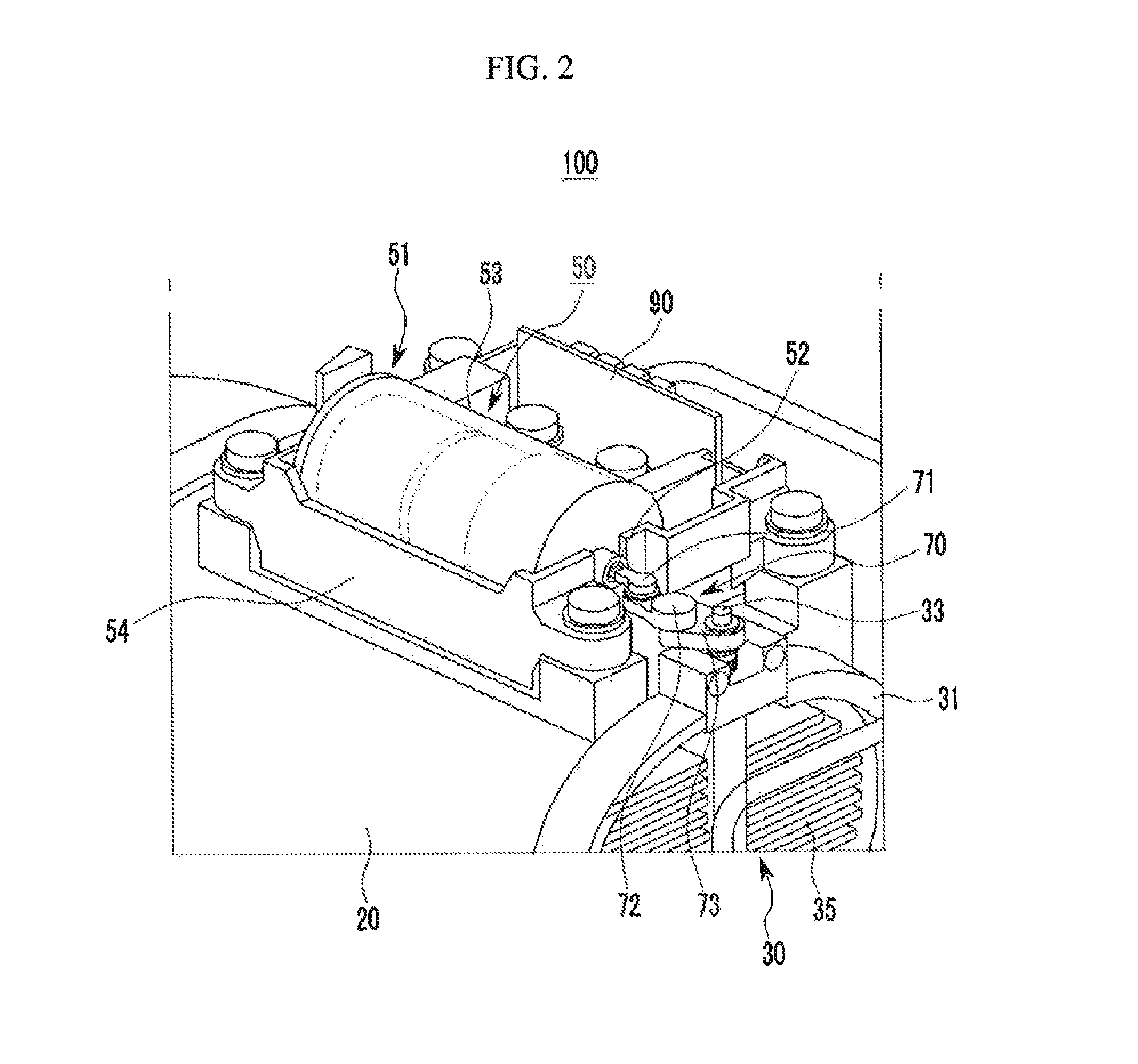
  • Variable intake system for vehicle, and apparatus and method for controlling the same
  • Variable intake system for vehicle, and apparatus and method for controlling the same
  • Variable intake system for vehicle, and apparatus and method for controlling the same

Examples


Embodiment Construction

[0040]Reference will now be made in detail to various embodiments of the present invention(s), examples of which are illustrated in the accompanying drawings and described below. While the invention(s) will be described in conjunction with exemplary embodiments, it will be understood that present description is not intended to limit the invention(s) to those exemplary embodiments. On the contrary, the invention(s) is / are intended to cover not only the exemplary embodiments, but also various alternatives, modifications, equivalents and other embodiments, which may be included within the spirit and scope of the invention as defined by the appended claims.

[0041]The drawings and description are to be regarded as illustrative in nature and not restrictive. Like reference numerals designate like elements throughout the specification.

[0042]The configurations shown in the drawings are arbitrarily given for convenience of the description, and the present invention is not necessarily limited ...


PUM


Abstract

An intake system mounted to a vehicle controls an opening angle of a variable flap according to an RPM of an engine, an intake pressure, and an opening angle of a variable flap to optimize performance in various operation regions by detecting engine RPM and an intake air pressure, and determining an operation region based on the RPM of the engine; applying the intake pressure to determine a target amount of air and an opening angle of a variable flap for an operation region; driving an actuator to adjust an opening angle of the variable flap to a target opening angle; and analyzing an operation position of the actuator to detect an opening angle of the variable flap, and, when the target opening angle is not followed, correcting a drive of the actuator such that an opening angle of the variable flap follows the target opening angle.

Description

CROSS-REFERENCE TO RELATED APPLICATION[0001]The present application claims priority of Korean Patent Application Number 10-2011-0127970 filed Dec. 1, 2011, the entire contents of which application is incorporated herein for all purposes by this reference.BACKGROUND OF INVENTION[0002]1. Field of Invention[0003]The present invention relates to an intake system mounted to a vehicle, and more particularly, to a variable intake system which optimally controls an angle of a variable intake valve according to an RPM of an engine, an intake pressure, and an opening angle of a variable flap to optimize performance in various operation regions, and an apparatus and a method for controlling the same.[0004]2. Description of Related Art[0005]A variable intake system mounted to a vehicle opens and closes an auxiliary duct according to a load of an engine to improve noise performance without causing loss of intake pressure.[0006]A variable intake system mounted to a vehicle according to the relate...

Claims


Application Information

Patent Timeline
Patent Type & Authority Patents(United States)
IPC IPC(8): F02M35/10
CPCF02D9/08F02B27/0273Y02T10/146F02M35/1222F02M35/1038F02D9/02F02M35/108F02D11/105F02M35/10013F02M35/0205F02D11/10Y02T10/12F02B27/02F02M35/02
Inventor LEE, SANG, IL
Owner HYUNDAI MOTOR CO LTD
Learn More