Method, device and program for setting threshold, and method, device and program for detecting target object

a threshold and threshold technology, applied in the field of threshold and threshold setting and methods, devices and programs for detecting target objects, can solve problems such as difficulty in determining thresholds

Inactive Publication Date: 2014-09-09
FURUNO ELECTRIC CO LTD
View PDF25 Cites 7 Cited by
  • Summary
  • Abstract
  • Description
  • Claims
  • Application Information

AI Technical Summary

Benefits of technology

[0007]Therefore, the present invention is made in view of the situations as described above, and provides a method of automatically and further accurately setting a threshold for discriminating a target object from a sea clutter as well as a noise, without being affected by whether the target object exists.
[0020]Here, not the method of setting the threshold along the distance direction simply at a single azimuth but the method of setting the threshold over the entire peripheral of the revolution of the antenna is described. That is, although the adaptive setting of the threshold for each position along the distance direction at the single azimuth may be performed for the entire azimuth, the setting of the threshold may be performed by the other method. In this method, the threshold setting is performed only at the particular azimuths set at the predetermined azimuth angle interval within the entire peripheral azimuth. Further, at each of the individual azimuths which are different from the particular azimuths, the threshold setting is performed by using the thresholds in the particular azimuths. Thereby, the threshold setting can be simpler than setting the threshold for each of the entire azimuth one by one.
[0022]Here, the specific contents of the interpolation in the method of setting the threshold over the entire periphery is described. By using this method, the interpolation can be performed by simple calculation processing.
[0024]In this method, the threshold is set adaptively to situations and, therefore, the echo of the target object can further accurately be discriminated.
[0026]In this method, the threshold is set adaptively to situations and, therefore, the echo signal of an unused component can further accurately be suppressed. Thereby, the echo of the unused component is suppressed and the detection image data in which the echo of the target object is clear can be created.

Problems solved by technology

Further, in a case where the number of sample echoes of the target object within an area where a histogram is calculated is small and / or a level difference between a clutter and the target object echo is small, a trough to clearly distinguish the target object from the clutter does not appear within the histogram, and therefore, it is difficult to determine the threshold.

Method used


Image

  • Method, device and program for setting threshold, and method, device and program for detecting target object
  • Method, device and program for setting threshold, and method, device and program for detecting target object
  • Method, device and program for setting threshold, and method, device and program for detecting target object

Examples


first embodiment

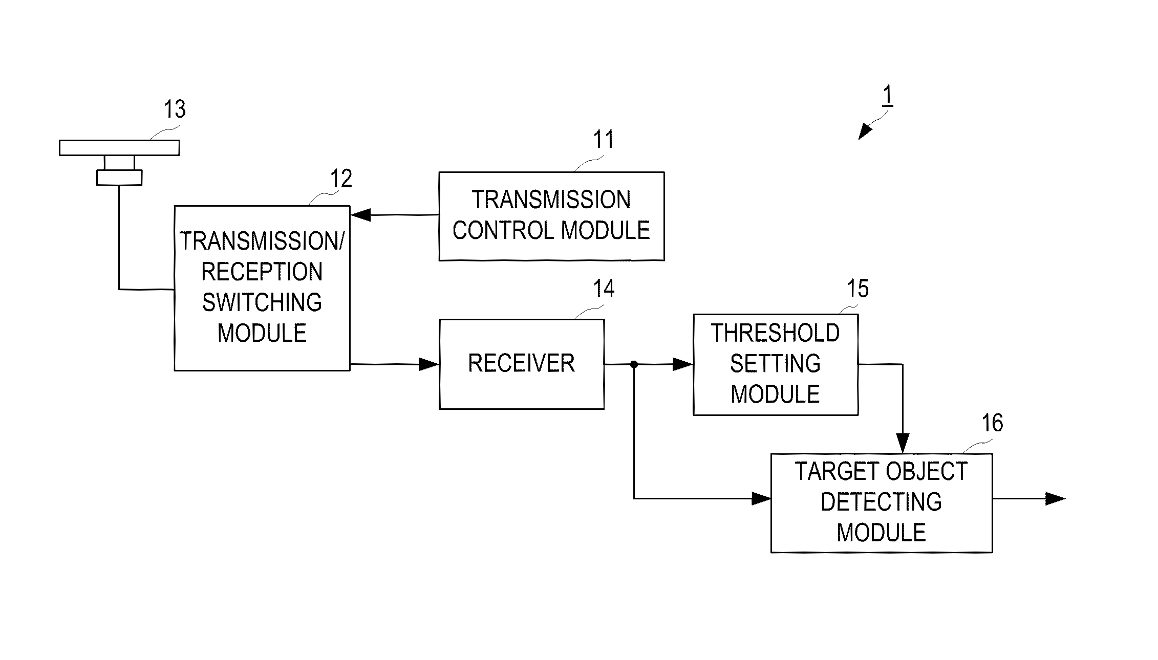
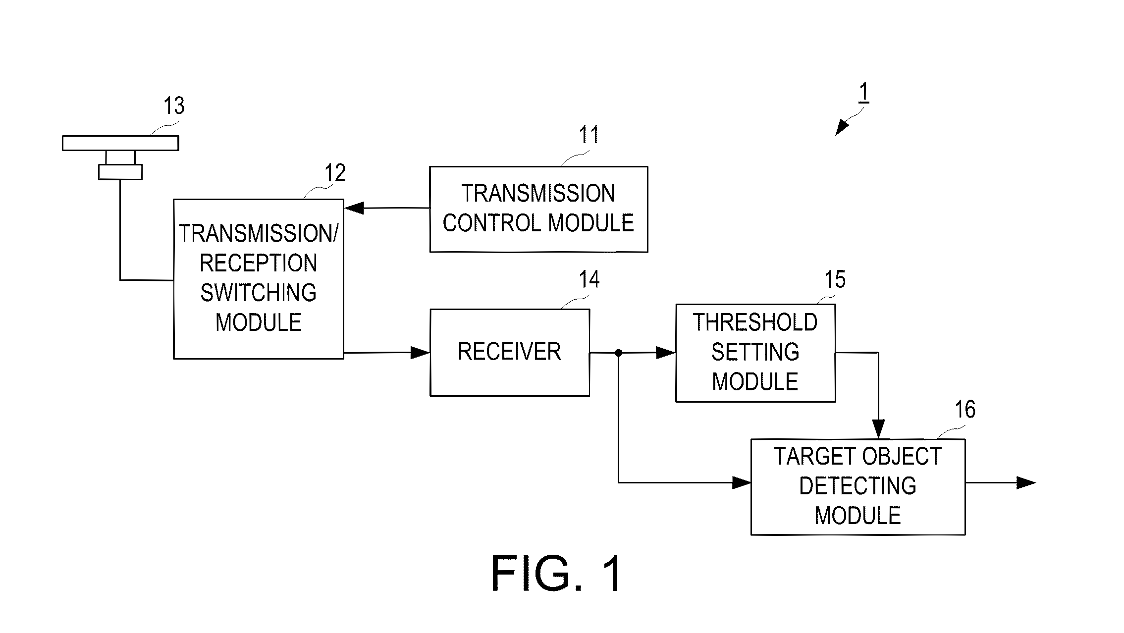
[0042]The target object detection device 1 includes a transmission control module 11, a transmission / reception switching module 12, an antenna 13, a receiver 14, a threshold setting module 15 corresponding to a threshold setting device of the invention, and a target object detecting module 16.

[0043]The transmission control module 11 generates a pulse shaped transmission signal at every predetermined transmission timing and outputs the transmission signal to the transmission / reception switching module 12. The transmission / reception switching module 12 outputs the transmission signal from the transmission control module 11 to the antenna 13.

[0044]The antenna 13 converts the transmission signal into a radio wave and emits outside while revolving at a predetermined revolving speed, and it further receives the radio wave from the outside, converts it into an electric signal to output as a reception signal to the transmission / reception switching module 12. The transmission / reception switc...

second embodiment

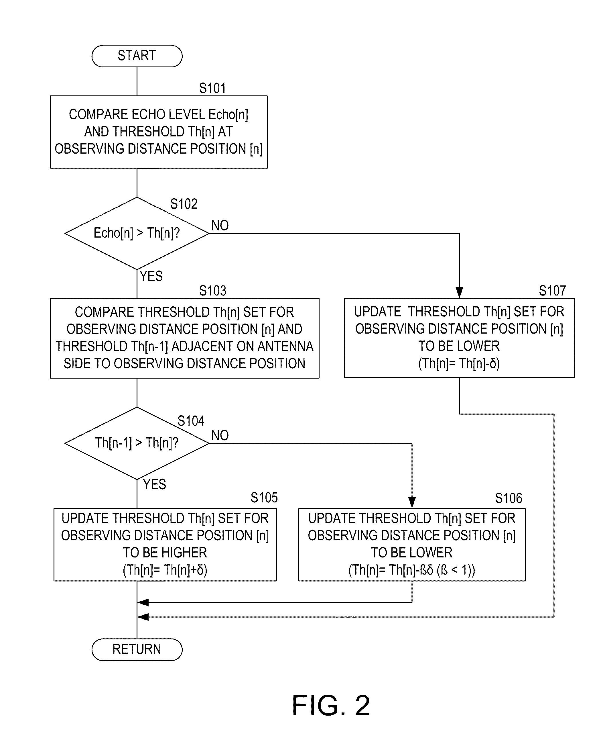
[0072]Next, a method of detecting a target object, the method including a method of setting the threshold, and a target object detection device equipped with a threshold setting device according to a second embodiment of the present invention is described in detail with reference to the accompanying drawings. In the method of setting the threshold, the setting of the threshold in an azimuth direction is described.

[0073]The method of setting the threshold according to the first embodiment is the method of adapting the thresholds set for respective distance positions along the same azimuth direction. Here, the antenna revolves as above and the target object detection device usually performs the target object detection for the entire periphery. Therefore, by performing the adaptation processing of the threshold for every azimuth direction (i.e., every sweep data), the adaptation processing of the threshold can be performed for the entire periphery. However, in this embodiment, the thre...


PUM


Abstract

This disclosure provides a method of setting a threshold according to a level of an echo signal containing an unused component. The echo signal is generated by transmitting and receiving a radio wave with an antenna while the antenna revolves. The method includes acquiring levels of the echo signals at every predetermined distance interval and updating a threshold set for an observing position based on the level of the echo signal at the observing position, the threshold set for the observing position, and a threshold set for a position closer to the antenna than the observing position by the predetermined distance on the same sweep.

Description

CROSS-REFERENCE TO RELATED APPLICATION(S)[0001]The application claims priority under 35 U.S.C. §119 to Japanese Patent Application No. 2010-153797, which was filed on Jul. 6, 2010 the entire disclosure of which is hereby incorporated by reference.TECHNICAL FIELD[0002]The present invention relates to a method of automatically setting a threshold for detecting a target object on the sea and a land by using a radio wave, and further relates to a method of detecting the target object by using the method of automatically setting the threshold.BACKGROUND OF THE INVENTION[0003]Conventionally, various target object detection devices for transmitting radio waves to detect a target object based on the echo signals of the transmitted radio waves have been devised. In such target object detection devices, for example a target object detection device equipped in a ship, a threshold for a target object detection may be set for discriminating a target object, such as another ship or a land, from a...

Claims


Application Information

Patent Timeline
Patent Type & Authority Patents(United States)
IPC IPC(8): G01S13/00G01S7/292G01S13/534G01S13/937
CPCG01S7/2927G01S13/534G01S13/9307G01S13/937
Inventor MAENO, HITOSHI
Owner FURUNO ELECTRIC CO LTD
Why Eureka
Try Eureka