Control system for reel mechanism

Inactive Publication Date: 2011-03-10
SUZOHAPP AMERICAS LLC
View PDF32 Cites 8 Cited by
  • Summary
  • Abstract
  • Description
  • Claims
  • Application Information

AI Technical Summary

Benefits of technology

[0017]Thus, there is a need for eliminating the need for manual phase setting in reel mechanisms in gaming machines and improving the method of monitoring and responding to conditions when the reel position drifts during a standstill condition and providing reel control mechanisms with improved operational abilities that are less expensive to manufacture.
[0018]The present invention relates to control system for eliminating known problems with reel mechanisms used in gaming machines. First of all, phase setting of the reel position is greatly simplified. More particularly, in accordance with one aspect of the invention, phase setting of the motor shaft in an unloaded position is obviated thus simplifying the overall

Problems solved by technology

In as much as there are normally five (5) reel mechanisms per gaming machine (number of reels in machine can be 3 to 7), phase setting of each of the reel mechanisms in a gaming machine (or at time of manufacture) is cumbersome and time consuming.
Failure to correct the offset in the zero position can result in the symbols on the reels not properly lining up with the pay lines on the gaming machines and with the symbols on the other reels in the machine.
Unfortunately, since gaming machines are configured so that the reel is directly coupled to the stepper motor on power up, the zero position will be offset.
Another problem with known reel mechanisms is the ability to control the reel position during a standstill condition.
There are several other problems with current methods of monitoring and controlling the reel position during a standstill condition.
First, the monitoring requires an optical sensor.
Second, during temporary power interruptions and low power conditions, the reels may drift from their stand

Method used


Image

  • Control system for reel mechanism
  • Control system for reel mechanism
  • Control system for reel mechanism

Examples


Example

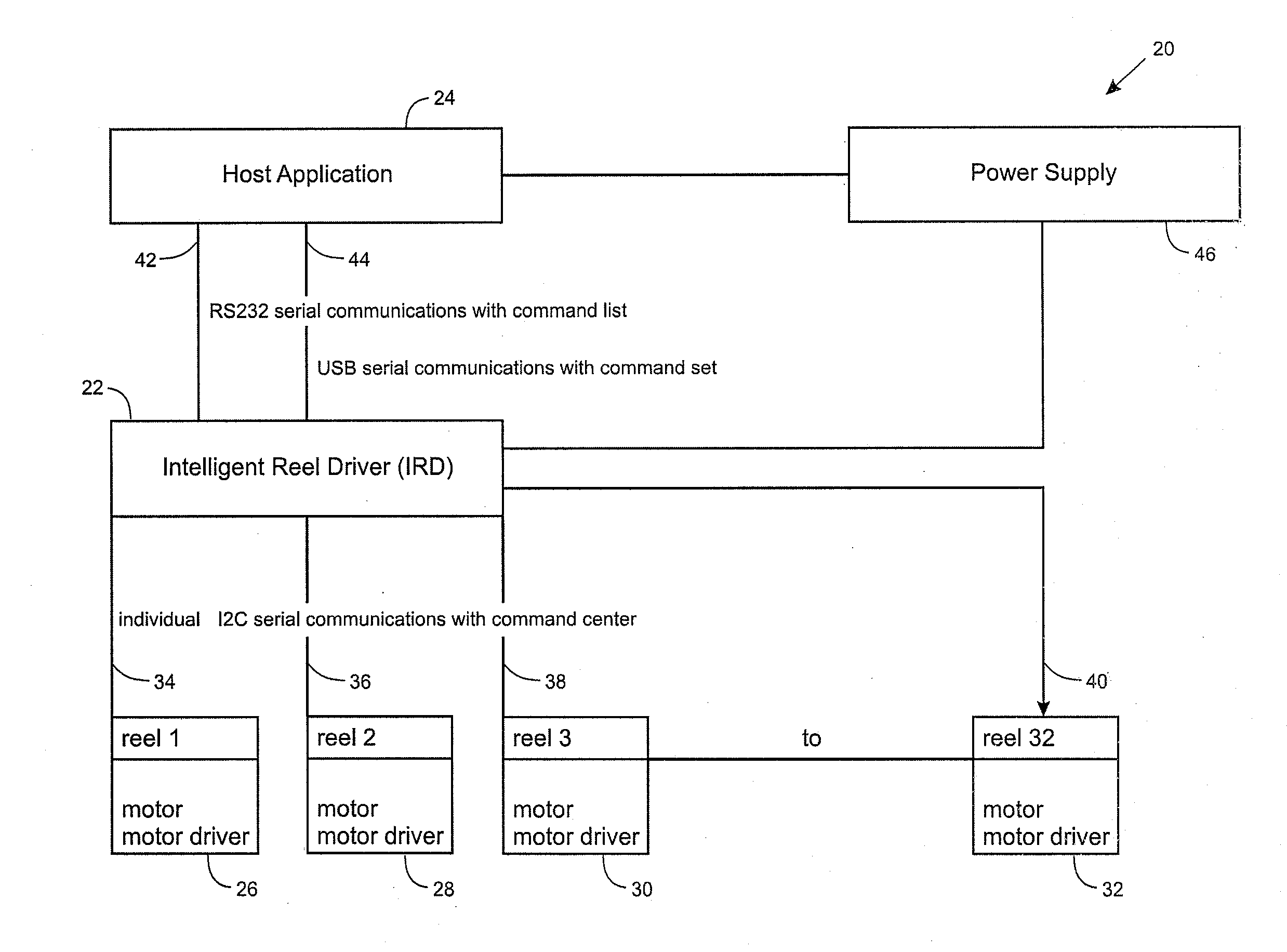
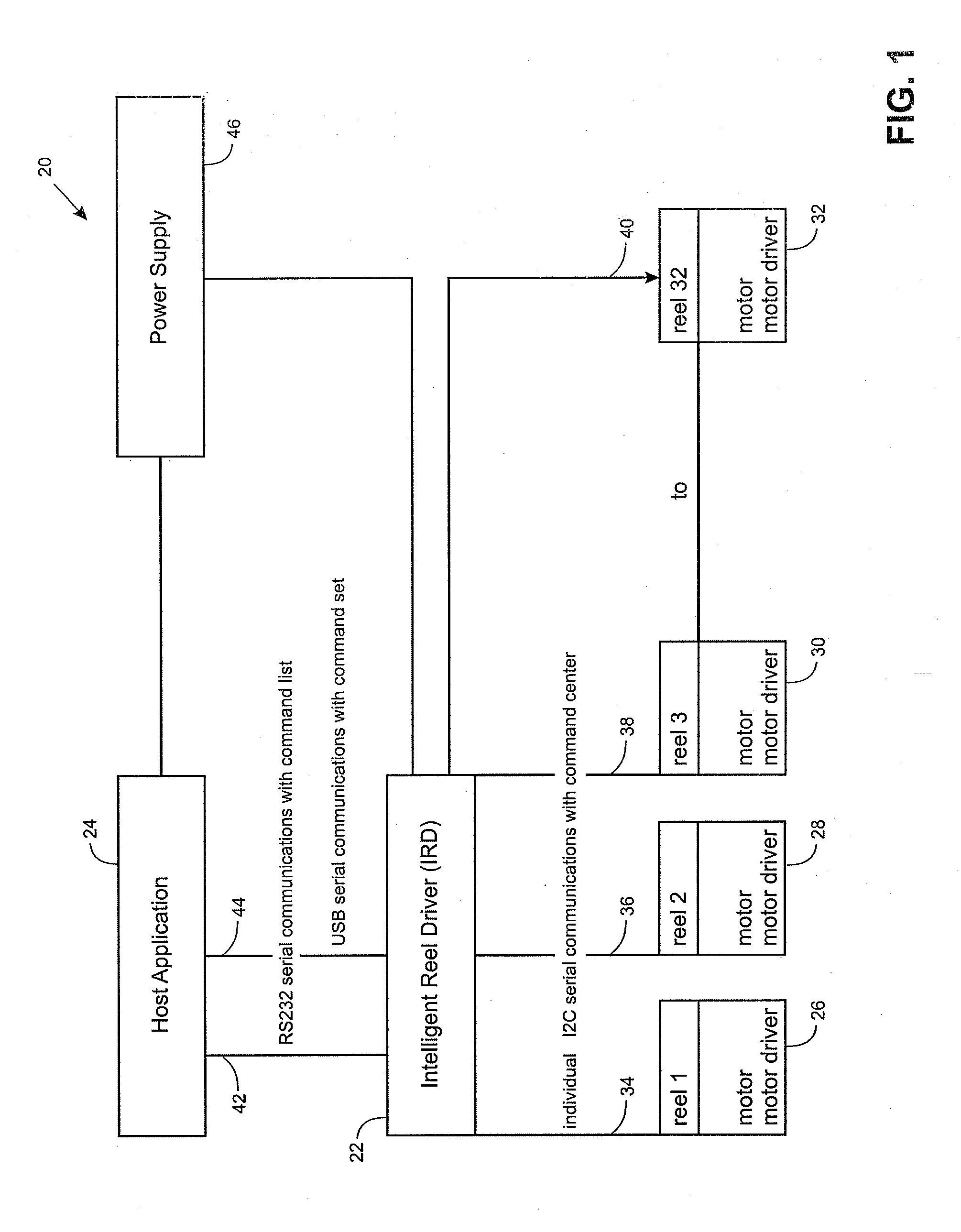
[0030]The present invention relates to a reel control system for a gaming machine having at least one reel mechanism, for example, as described in detail in U.S. Pat. Nos. 4,410,178 and 5,388,829, hereby incorporated by reference. As will be discussed in detail below, the control system in accordance with the present invention relates to a reel control system that includes various improvements relative to known reel control systems.

[0031]For example, the reel control system is configured to eliminate known problems related to phase setting and detection of reel movement during a standstill condition. In accordance with another aspect of the invention, the reel control system may also be configured to enable reels with unequal symbol lengths to be utilized which enabled the odds of a winning combination to be easily changed. In accordance with yet another aspect of the invention, the reel control system is configured to control multiple stepper motor drivers by way of a single serial...


PUM


Abstract

A reel control system is disclosed for eliminating known problems with reel mechanisms used in gaming machines. First of all, phase setting of the reel position is greatly simplified. The control system also provides a relatively accurate method for determining if a reel position has moved from a standstill position, due to low power, no power or outright tampering. Any movement of the reel can be corrected. The reel control system is also configured with multiple serial bus interfaces connected to a single serial bus that, in turn, can be connected to multiple stepper motor drivers which provides for fast response time to commands. In accordance with other aspects of the invention, the reel control system can drive multiple stepper motor drivers configured with the same physical address to reduce manufacturing costs and is further configured to simultaneously drive multiple reels, different distances, different directions, with different numbers of symbols per reel as well as drive different types of reels.

Description

CROSS REFERENCE TO RELATED APPLICATIONS[0001]This application claims priority to and the benefit of U.S. Patent Application No. 61 / 240,755, filed on Sep. 9, 2009, hereby incorporated by reference.BACKGROUND OF THE INVENTION[0002]1. Field of the Invention[0003]The present invention relates to a reel control system for a gaming machine with multiple reels and more particularly to a reel control system which facilitates factory calibration of the radial position of the motor shaft to a home position on initial power up and automatically resets the home position on subsequent power-ups and maintains the standstill position of the reel mechanism while enabling unequally spaced symbols. The reel control system is also configured to drive a plurality stepper motor drivers virtually simultaneously by way of a serial bus with multiple serial interfaces. In accordance with another important aspect of the invention, the reel control system can drive multiple reels, different distances, differe...

Claims


Application Information

Patent Timeline
IPC IPC(8): A63F9/24
CPCG07F17/3202G07F17/34G07F17/3211
Inventor CROSSMAN, COLINJEFFS, ANTHONY
Owner SUZOHAPP AMERICAS LLC
Why Eureka
Try Eureka