
Home appliance with unitary broil element mount and reflector

a technology of unitary broil element and reflector, which is applied in the field of home appliances, can solve the problems of difficult installation and removal during repair, and achieve the effect of simple installation and removal

Active Publication Date: 2014-09-16
BSH HOME APPLIANCES CORP
View PDF1 Cites 6 Cited by
  • Summary
  • Abstract
  • Description
  • Claims
  • Application Information

AI Technical Summary

Benefits of technology

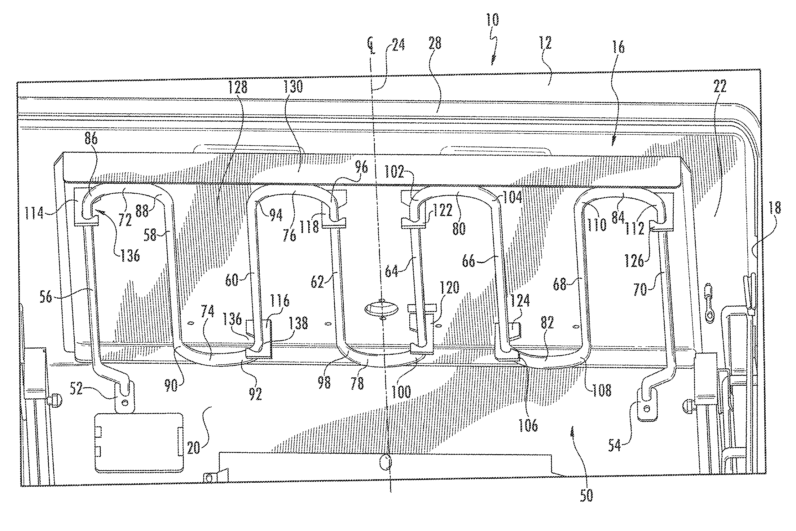
The present invention is a new way of putting a broil element in an oven. It makes it easier to install and remove, and keeps the element in place while it's heating. This saves money because separate brackets and wireforms don't need to be used.

Problems solved by technology

In the past, such broil elements have been difficult to install which also means that they are difficult to remove and replace during repair.
As explained more fully below, the old method used two separate brackets that were attached to the reflector with screws that pass into the top wall of the cavity that make installation difficult.

Method used


Image

  • Home appliance with unitary broil element mount and reflector
  • Home appliance with unitary broil element mount and reflector
  • Home appliance with unitary broil element mount and reflector

Examples


Embodiment Construction

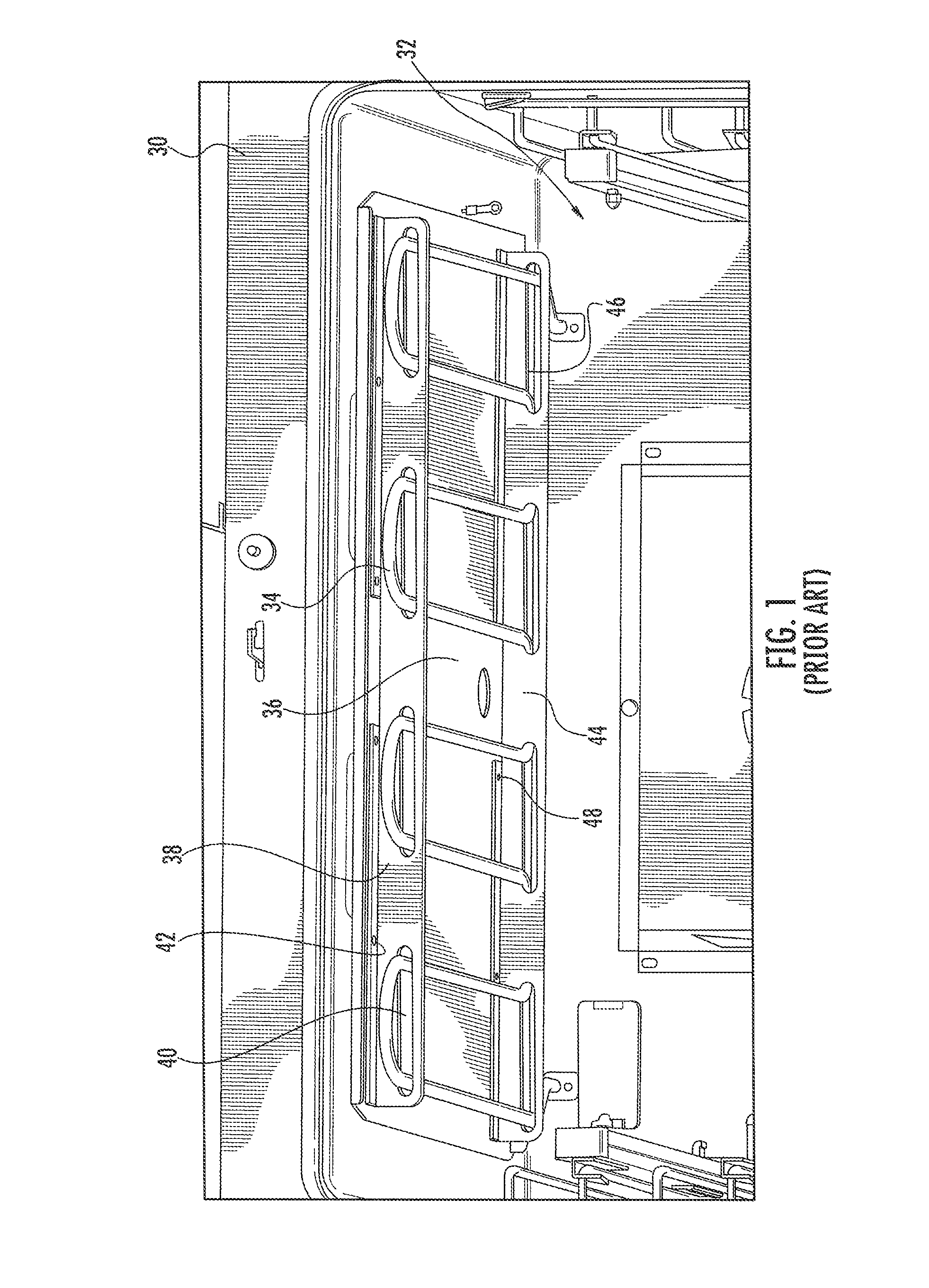
[0030]Turning now to the drawings and, more particularly to FIG. 1, a prior art range is illustrated at 30 and defines an oven cavity. A resistive broil element 34 is mounted to a top wall of the oven cavity 32 for heating and cooking food on a rack (not shown) below the broil element 34. The broil element 34 is plugged into electrical connections at the rear of the oven 32. As is known with resistive cooking elements, the broil element is serpentine in shape and, due to the mounting structure, appears in FIG. 1 as a series of four U-shaped members. Nevertheless, it will be understood by those skilled in the art that connecting portions of the broil element 34 are hidden due to the bracket structure and a single, tubular rod forms the serpentine broil element.

[0031]The broil element 34 is mounted to a reflector 36 that is in turn mounted to the top wall of the oven 32 using two brackets 38, 44. A front bracket 38 is a generally elongate planar member that extends traversely across t...


PUM


Abstract

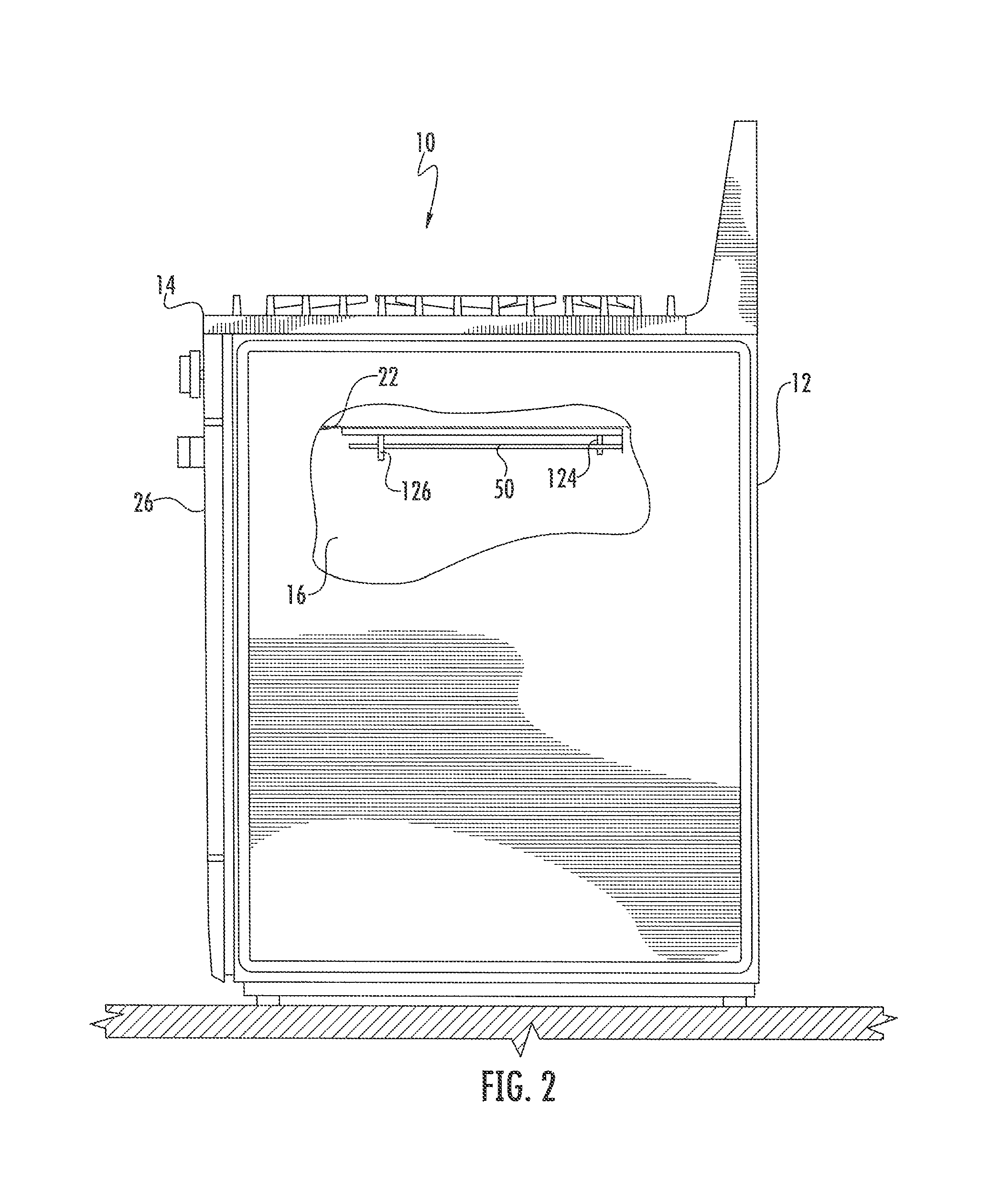
A home appliance having an oven with a broil element, the home appliance including an appliance body; an oven cavity defined within the appliance body; a broil element mounted within the oven cavity; a broil element reflector mounted to a wall of the oven cavity; and a mounting arrangement formed integrally with the broil element reflector for mounting the broil element within the oven cavity.

Description

BACKGROUND OF THE INVENTION[0001]The present invention relates broadly to home appliances having ovens with electric resistive broil elements and, more particularly, to a home appliance, particularly a range, having an improved mounting arrangement for a broil element.[0002]Most every electric range that includes an oven has internal resistive bake and broil elements which are generally curved tubular members that produce heat upon electrical activation. The bake elements are mounted to the floor of the oven cavity while the broil elements are mounted to the roof or top wall of the oven cavity. Typically, a reflector element will be between the broil element and the top wall of the oven for enhanced heating and for mounting the broil element to the oven cavity.[0003]In the past, such broil elements have been difficult to install which also means that they are difficult to remove and replace during repair. As explained more fully below, the old method used two separate brackets that ...

Claims


Application Information

Patent Timeline
Patent Type & Authority Patents(United States)
IPC IPC(8): A21B1/00F27D11/00
CPCF24C7/065F24C7/06
Inventor BRADEN, BENHANNA, CHARLIERUSSELL, TIMOTHY
Owner BSH HOME APPLIANCES CORP
Learn More