Brake Actuation Mechanism For A Disc Brake And Disc Brake Comprising The Same

a technology of disc brake and actuation mechanism, which is applied in the direction of actuators, slack adjusters, braking elements, etc., can solve the problems of slack, counter-torque, and decrease of wear-induced distance, so as to achieve more cost-effective production, installation and maintenance, and more reliable operation. , the effect of compact design

Inactive Publication Date: 2017-05-04
HALDEX BRAKE PROD AB
View PDF1 Cites 6 Cited by
  • Summary
  • Abstract
  • Description
  • Claims
  • Application Information

AI Technical Summary

Benefits of technology

[0017]It is therefore an object of the present invention to provide an enhanced brake actuation mechanism preferably of the single tappet design as described above comprising an adjustment mechanism, in which particularly the afore-mentioned drawback of undesired reverse motion of the adjuster is eliminated. The newly developed brake actuation mechanism shall be more cost-efficient to produce, to install and to maintain and shall be more compact in design and shall provide a more reliable functioning.
[0063]Beside this locking function during brake release, the second wrap spring in the brake release state also serves to prevent any undesired backward rotation of the adjustment spindle which may be caused by vibrations.
[0065]Thus, the brake adjustment mechanism and the disc brake according to the invention provides for rotational locking against undesired backward rotation at brake release and against any rotations caused by vibrations. This is achieved without any extra friction resistance between threaded components of the adjustment mechanism or parts connected thereto, which would otherwise cause increased loads on components being involved in the adjusting process. In turn, this allows that all other components of the brake actuation mechanism and particular the adjustment mechanism incorporated therein can be designed and manufactured with lowest possible friction resistances. This will further reduce the required driving torque for adjustments and by that reduce the stress and thus failure risk for components being under load in this functional phase.
[0066]The brake actuation mechanism is therefore more reliable. Furthermore, it realizes a very compact design since all components being arranged around the central rod are more or less rotationally symmetric and can thus be manufactured in a very cost-effective way and since the clutch elements do spatially overlap without contacting each other and provide double functions. Furthermore, the rotatable output element, i.e. the clutch sleeve, which is rotationally connected to the adjustment spindle, serves as a radial outer clutch part for both the first wrap spring and the second wrap spring, providing an even more compact design of the entire brake actuation mechanism.

Problems solved by technology

Namely, if the friction linings do wear to such an extent that the running clearance is greater than the target clearance, the existing running clearance between the brake pad and the brake disc is taken up and the further additional movement of the brake pad towards the brake disc, which results from and thus corresponds to the actually existing excessive lining wear, causes the clutch to rotate, which rotation will advance the brake pad towards the brake disc.
Furthermore, the adjustment mechanism comprises a torque limiting clutch mechanism slipping or overrunning when the rotational resistance between the threaded parts rises due to the axial force, which is built up when the brake pad contacts the brake disc, thereby creating some kind of counter-torque.
The advantage to combine these two functions by one element, however, is accompanied by the drawback that a rather large friction torque in the free-running direction of the section aiming at the one-way clutch function has to be provided which is due to the fact that the dimensions of the wire used for winding the wrap spring have to be selected to be rather large, so that a high enough and well defined driving torque at brake actuation can be transmitted in any case.
Accordingly, there exists the drawback that the slack, which corresponds to a decrease of the wear-induced distance between the brake disc and the brake pad / lining, as previously set by the adjustment mechanism during brake actuation will be again increased, even though to a minor extent as compared to the clearance reduction, by the return motion inherently resulting from the torque limiting clutch mechanism.
The problem of some undesired backlash motion, anyway, more or less exists for all kind of automatic brake adjusters in the prior art.
However, considering the forces and torques being present in disc brakes such measures usually have proven to be not enough, so that there may be the further need to introduce an extra friction resistance somewhere between components of the adjustment mechanism or of the brake actuation mechanism which are moveable relative to each other.
In turn, however, such increase of the inherent frictional resistance in the mechanism would again require a higher driving torque from the entire torque limiting clutch mechanism, which may call for larger wire dimensions, which, however, will then counteract the need to have a free-running torque in the one-way clutch section of the wrap spring which shall be as low as possible.

Method used


Image

  • Brake Actuation Mechanism For A Disc Brake And Disc Brake Comprising The Same
  • Brake Actuation Mechanism For A Disc Brake And Disc Brake Comprising The Same
  • Brake Actuation Mechanism For A Disc Brake And Disc Brake Comprising The Same

Examples


Embodiment Construction

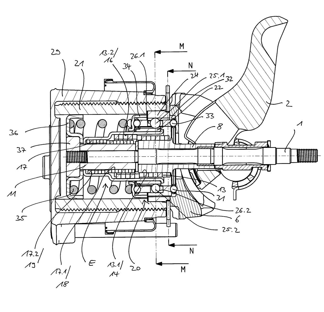
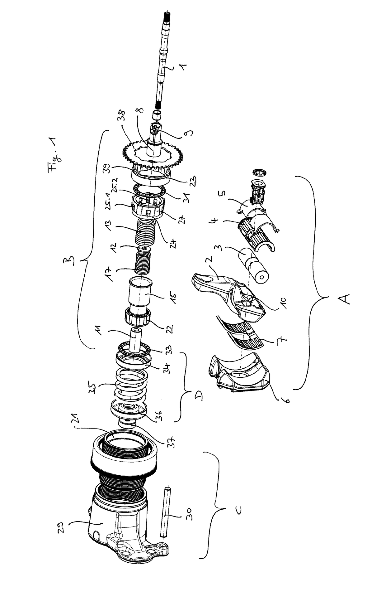
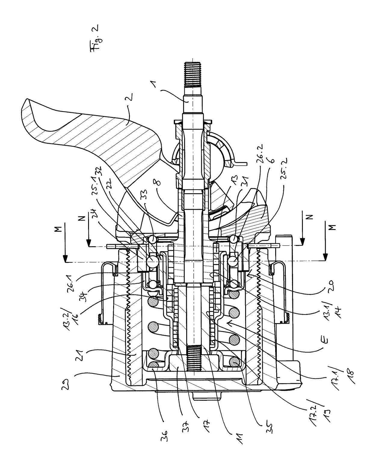
[0072]The brake actuation mechanism according to the invention, which is to be received in the housing of a brake caliper of a disc brake, substantially comprises an amplification mechanism A, which introduces an actuating force originating from an hydraulic, pneumatic or electro-mechanical actuator (not shown herein) as a clamping force into the brake actuation mechanism and thereby enforcing it in correspondence with a gear ratio being determined by its construction, an adjustment mechanism B, which serves for compensation of brake lining wear, a thrust element C, which transmits the enforced clamping force onto the brake disc, and a reset device or return mechanism Din order to return the brake actuation mechanism in its starting position, in case no brake force is applied anymore by the actuator.

[0073]These above-mentioned assembly groups A, B, C and D are arranged on one central rod 1, which is aligned in parallel to the axis of the brake disc (not shown) The rod 1 serves as mo...


PUM


Abstract

A brake actuation mechanism for a disc brake including an amplification mechanism, an adjustment mechanism, a thrust element and a return mechanism, which are mountable inside a caliper housing by way of a rod so as to be functionally interacting, in which the adjustment mechanism includes a torque limiting clutch mechanism drivingly connecting several elements and including a first clutch element drivingly connecting a rotatable input element with a rotatable output element and a second clutch element connecting the rotatable output element with the rod, the rotatable output element radially surrounding the first clutch element and the second clutch element. A disc brake including such brake actuation mechanism is also contemplated.

Description

FIELD OF THE INVENTION[0001]The present invention relates to a brake actuation mechanism for a disc brake and to a disc brake, in particular for an utility vehicle, which comprises such brake actuation mechanism.BACKGROUND OF THE INVENTION[0002]In this connection the invention shall include disc brakes which either comprise a sliding caliper or a fixed caliper, which overlap one or more brake discs. Mainly but not exclusively the invention relates to disc brakes with lining sections of the spot-type.[0003]Disc brakes, in particular for heavy load trucks, are known with different configurations, both with respect to the type of the actuation mechanism, with respect to the way of the transmission of the braking or clamping force onto one or several brake discs and with respect to the type of the adjustment for compensating the wear of the brake pad and / or the brake disc.[0004]Generally, there exists a wide range of actuation mechanism and brake adjuster designs applied and embodied in...

Claims


Application Information

Patent Timeline
Patent Type & Authority Applications(United States)
IPC IPC(8): F16D65/18F16D65/56
CPCF16D65/18F16D2125/28F16D2125/582F16D65/567F16D66/026F16D2121/14
Inventor SANDBERG, STEFAN
Owner HALDEX BRAKE PROD AB
Why Eureka
Try Eureka