Leaky-wave dual-antenna system

a dual-antenna and leaky wave technology, applied in the structural form of radiating elements, leaky waveguide antennas, resonance antennas, etc., can solve the problem of more signal leakage, achieve the effect of reducing the maximum coupling factor, reducing the coupling factor, and improving the gain of the antenna

Active Publication Date: 2010-06-24
NAT CHUNG SHAN INST SCI & TECH
View PDF2 Cites 6 Cited by
  • Summary
  • Abstract
  • Description
  • Claims
  • Application Information

AI Technical Summary

Benefits of technology

[0011]According to another embodiment, the length of each of the plural first microstrips is different, and the length of each of the plural second microstrips is different. The leaky-wave dual-antenna system of the invention is located in a medium (such as air), the length difference between two adjacent first microstrips next to each other and the length difference between two adjacent second microstrips next to each other are all shorter than λg / 2, wherein λg=λ0 / (εg)1 / 2, λg is the wave length of the electromagnetic wave in the medium, λ0 is the wave length of the electromagnetic wave in a vacuum, and εg is the dielectric constant of the medium. Thereby, the plural microstrips with different lengths (namely, the load impedances of the plural microstrips are mismatching) make the corresponding frequency of the maximum coupling quantity under the operating frequency band shift to a further higher frequency (deviate from the operating frequency band) and stagger the corresponding frequency of the maximum radiation energy approximately equal to the operating frequency band, to reduce the maximum coupling factor under the operating frequency band.
[0012]In summary, the transmitting antenna array and the receiving antenna array of the present invention are constituted by plural leaky-wave antennas respectively to improve the gain of the antenna and reduce the coupling factor between the transmitting antenna array and the receiving antenna array. Furthermore, the corresponding frequency of the maximum coupling quantity is shifted to a slightly higher frequency by means of an L-type matching network of the differential circuits and the microstrips. Furthermore, the corresponding frequency of the maximum coupling quantity is shifted to an even higher frequency by means of the microstrips with different lengths to stagger the corresponding frequency of the maximum radiation energy. In other words, the main purpose of the leaky-wave dual-antenna system is to shift the corresponding frequency of the maximum coupling factor under the operating frequency band to a further higher frequency (deviate from the operating frequency band) and stagger the corresponding frequency of the maximum radiation energy (approximately equal to the operating frequency band) to reduce the maximum coupling factor under the operating frequency band, namely, to improve the mutual coupling S21 of the leaky-wave dual-antenna system. Moreover, the design of the antenna with different lengths of the present invention can not only reduce the coupling effect of the antenna system in a confined space, but also allow more antenna elements to be installed in a confined space to improve the gain of the antenna.

Problems solved by technology

Also, the impedance mismatch between antenna and circulator will also result in more signal leakage.

Method used


Image

  • Leaky-wave dual-antenna system
  • Leaky-wave dual-antenna system
  • Leaky-wave dual-antenna system

Examples


Embodiment Construction

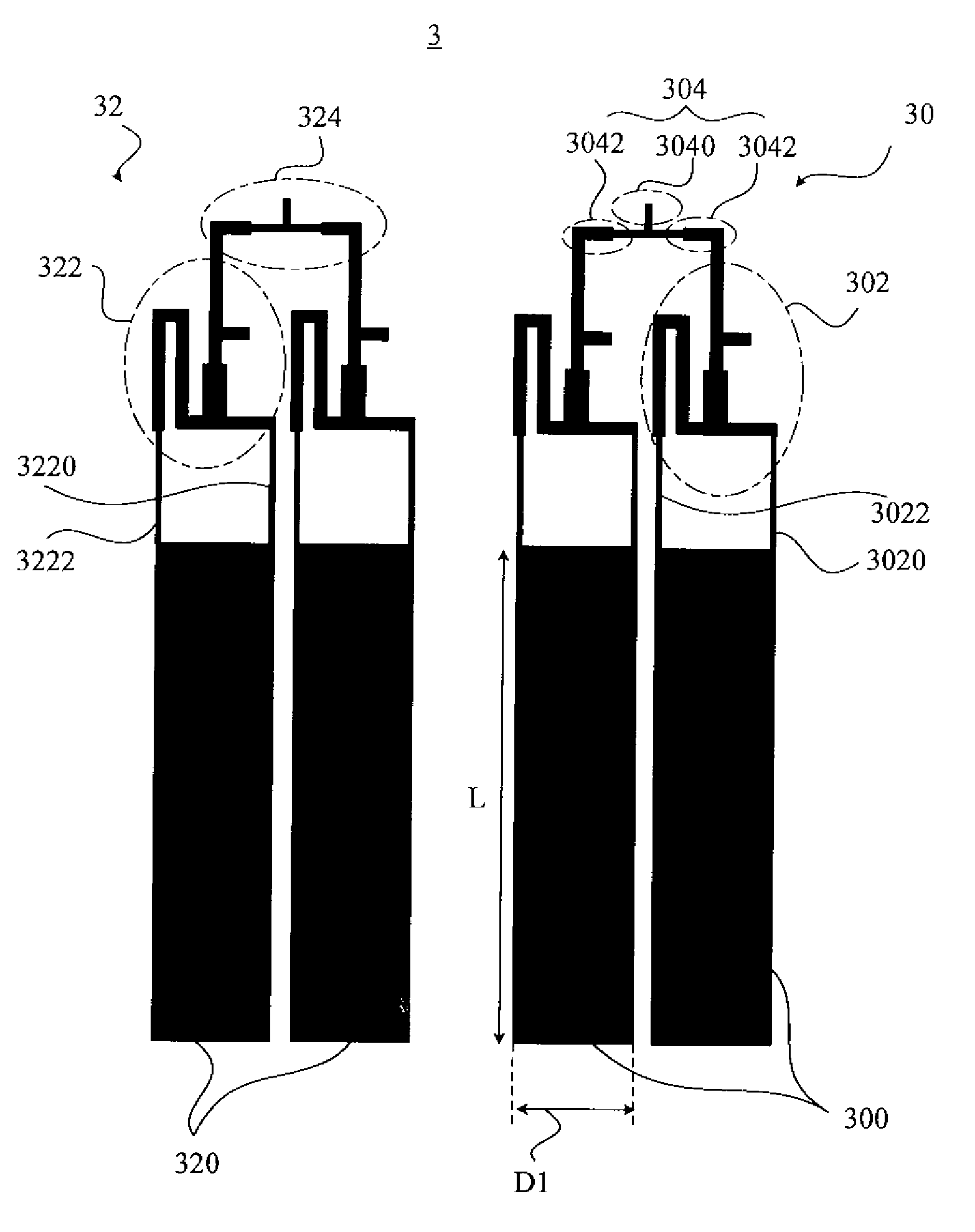
[0024]FIG. 4A illustrates a leaky-wave dual-antenna system 3 according to the first embodiment of the present invention. As illustrated in FIG. 4A, the leaky-wave dual-antenna system 3 of the invention comprises a transmitting antenna array 30 and a receiving antenna array 32. The transmitting antenna array 30 is used for transmitting an electromagnetic wave to a detection target. The transmitting antenna array 30 comprises two first microstrips 300 and two corresponding first differential circuits 302, and each of the first differential circuit 302 matches the corresponding first microstrip 300 by an L-type matching network. The receiving antenna array 32 is for receiving the reflected electromagnetic wave after transmitted by the transmitting antenna array 30 to the detected target. The receiving antenna array 32 comprises two second microstrips 320 and two corresponding second differential circuits 322, and each of the second differential circuit matches 322 the corresponding sec...


PUM


Abstract

The invention discloses a leaky-wave dual-antenna system comprising a transmitting antenna array and a receiving antenna array. The transmitting antenna array comprises plural first microstrips and plural corresponding first differential circuits, and each of the first differential circuit matches the corresponding first microstrip by a L-type matching network; the receiving antenna array comprises plural second microstrips and plural corresponding second differential circuits, and each of the second differential circuit matches the corresponding second microstrip by a L-type matching network. A first end and a second end of each of the first differential circuits are respectively connected to the corresponding first microstrip; a third end and a fourth end of each of the second differential circuits are respectively connected to the corresponding second microstrip.

Description

BACKGROUND OF THE INVENTION[0001]1. Field of the Invention[0002]The present invention relates generally to a dual-antenna system, and more particularly, the present invention relates to a leaky-wave dual-antenna system which can improve the mutual coupling S21, or isolation between antennas.[0003]2. Description of the Prior Art[0004]A conventional frequency-modulated continuous-wave (FM-CW) radar uses a single-antenna with a circulator or a dual-antenna structure to isolate the leakage power between transmitting and receiving ends. Furthermore, a leaky-wave type antenna with differential input could be used to further enhance the isolation effect. In the single antenna with a circulator design, the isolation between transmitting and receiving end is around −35 dB, and amplifiers can not be used between antenna and circulator. Also, the impedance mismatch between antenna and circulator will also result in more signal leakage. A dual-antenna structure has advantages of better isolatio...

Claims


Application Information

Patent Timeline
Patent Type & Authority Applications(United States)
IPC IPC(8): H01Q21/00H01Q1/50
CPCH01Q13/20H01Q1/525
Inventor CHANG, CHI-HOLIU, FENG-LINGYANG, PEI-JILO, MIN-FANG
Owner NAT CHUNG SHAN INST SCI & TECH
Why Eureka
Try Eureka