Storage battery charge circuit

a charge circuit and storage battery technology, applied in the direction of charge maintainance charging/discharging, electric vehicles, transportation and packaging, etc., can solve the problem of complex structure of such a charge circui

Inactive Publication Date: 2014-09-16
FU TAI HUA IND SHENZHEN +1
View PDF8 Cites 2 Cited by
  • Summary
  • Abstract
  • Description
  • Claims
  • Application Information

AI Technical Summary

Benefits of technology

[0004]It is known that when a storage battery such as a lead-acid battery discharges, lead sulfate forms on the battery's plates. When the lead sulfate reaches a certain amount, the battery may be no longer used. In order to prolong the service life of the battery, during the charging of the battery, a charge circuit charges the battery for a relatively longer time and causes the battery to discharge for a relatively shorter time alternately, to reduce lead sulfate on the battery's plate. However, the structure of such a charge circuit is usually complex. Therefore, it is desirable to provide a simple storage battery charge circuit.

Problems solved by technology

However, the structure of such a charge circuit is usually complex.

Method used


Image

  • Storage battery charge circuit
  • Storage battery charge circuit

Examples


Embodiment Construction

[0007]The disclosure is illustrated by way of example and not by way of limitation. It should be noted that references to “an” or “one” embodiment in this disclosure are not necessarily to the same embodiment, and such references mean at least one.

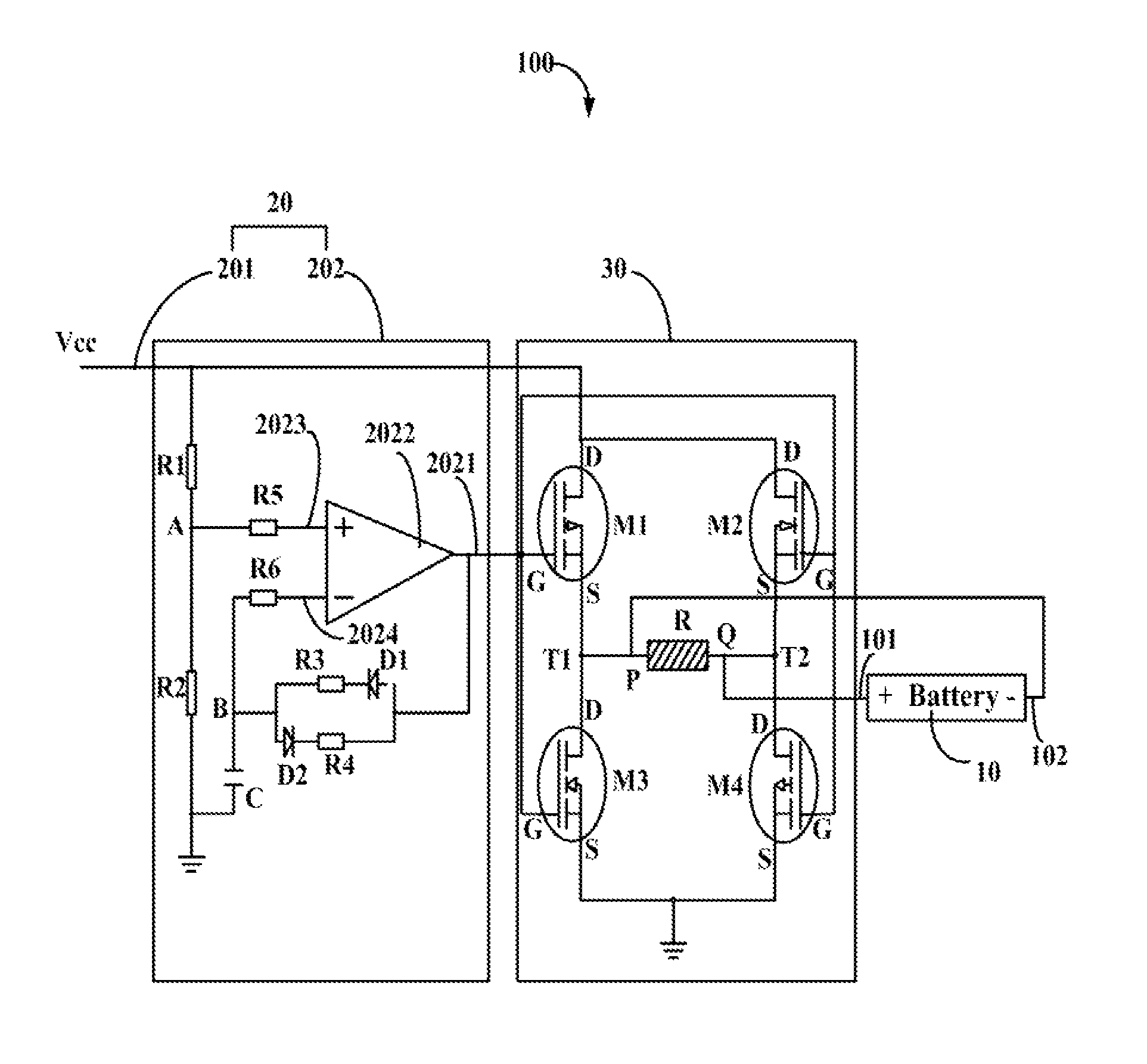
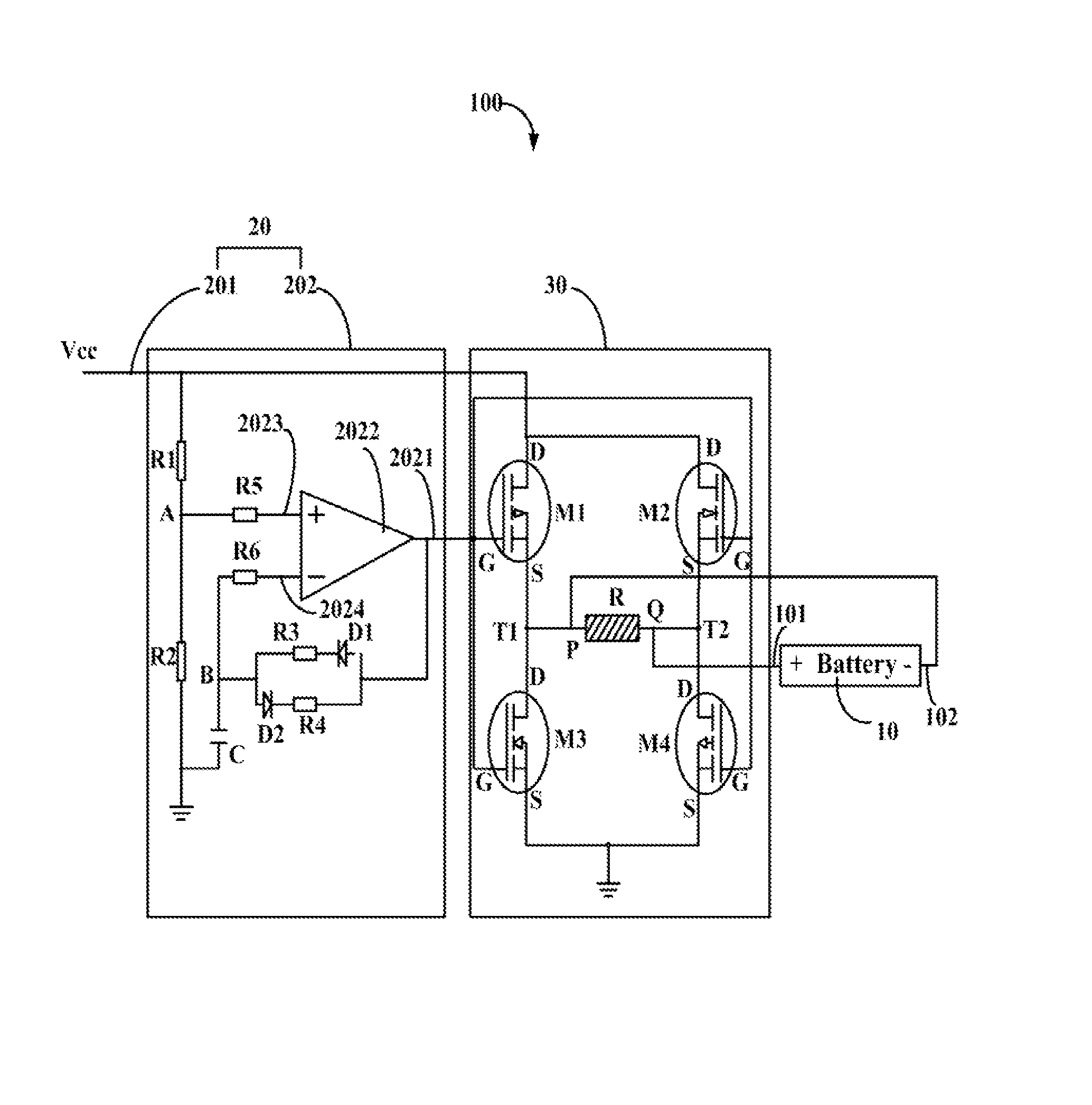
[0008]Referring to the drawing, a storage battery charge circuit 100 charges a storage battery 10. The circuit 100 includes a control signal output circuit 20 and a charge circuit 30. The control signal output circuit 20 includes a voltage input port 201 and a converting circuit 202. The voltage input port 201 is connected to a power source to receive a logic high level voltage. The converting circuit 202 is connected to the input port 201 to convert the received logic high level voltage to a control signal including a logic high level voltage and a logic low level voltage alternately. In addition, a mark space ratio of the control signal is not equal to one, that is, the duration of the logic high level voltage is different from the durat...


PUM


Abstract

A storage battery charge circuit for charging a battery is provided. The circuit includes a voltage input port, a converting circuit, and a charge circuit. The voltage input port is for being connected to a power source to receive a logic high level voltage. The converting circuit is connected to the voltage input port to convert the received logic high level voltage into a control signal including a logic high level voltage and a logic low level voltage alternately and the mark space ratio is not equal to one. The charge circuit is connected to the converting circuit to charge the battery or discharge the battery according to the control signal.

Description

BACKGROUND[0001]1. Technical Field[0002]The present disclosure relates to a storage battery charge circuit.[0003]2. Description of Related Art[0004]It is known that when a storage battery such as a lead-acid battery discharges, lead sulfate forms on the battery's plates. When the lead sulfate reaches a certain amount, the battery may be no longer used. In order to prolong the service life of the battery, during the charging of the battery, a charge circuit charges the battery for a relatively longer time and causes the battery to discharge for a relatively shorter time alternately, to reduce lead sulfate on the battery's plate. However, the structure of such a charge circuit is usually complex. Therefore, it is desirable to provide a simple storage battery charge circuit.BRIEF DESCRIPTION OF THE DRAWINGS[0005]The components in the drawing are not necessarily drawn to scale, the emphasis instead being placed upon clearly illustrating the principles of the present disclosure.[0006]The...

Claims


Application Information

Patent Timeline
Patent Type & Authority Patents(United States)
IPC IPC(8): H02J7/00
CPCH02J7/0057H02J7/0069
Inventor ZHANG, JUN-WEIWONG, SHIH-FANGCHUANG, TSUNG-JENZHANG, JUNCHIEN, CHIA-HUNGWANG, CHUNG-JEN
Owner FU TAI HUA IND SHENZHEN
Why Eureka
Try Eureka