
Quick correction device for a display system

a display system and quick correction technology, applied in mechanical clocks, instruments, horology, etc., can solve problems such as stress in the gear train and difficulty in correcting the display member

Active Publication Date: 2014-09-16
MONTRES BREGUET
View PDF11 Cites 7 Cited by
  • Summary
  • Abstract
  • Description
  • Claims
  • Application Information

AI Technical Summary

Benefits of technology

[0004]It is an object of the present invention to overcome all or part of the aforecited drawbacks by proposing a quick correction device which is totally integrated in the gear train of the display system and capable of correcting the display member at any time without generating stress in the gear train of the measuring system.
[0006]Advantageously according to the invention, it is clear that the correction device can thus correct the display at any time without inducing any stress in the gear train liable to interfere with the working of the measuring system. It is to be noted in particular that no problems arise in coupling the correction device to a rotating gear train. Finally, the correction device is advantageously very well integrated in the gear train, i.e. it is very compact.

Problems solved by technology

Current mechanisms may make it difficult to correct the display member, such as the calendar, in proximity to the change of the display member and require the use of a safety device to avoid damage.
Moreover current correction devices may cause stress in the gear train when the display is corrected.

Method used


Image

  • Quick correction device for a display system
  • Quick correction device for a display system
  • Quick correction device for a display system

Examples


Embodiment Construction

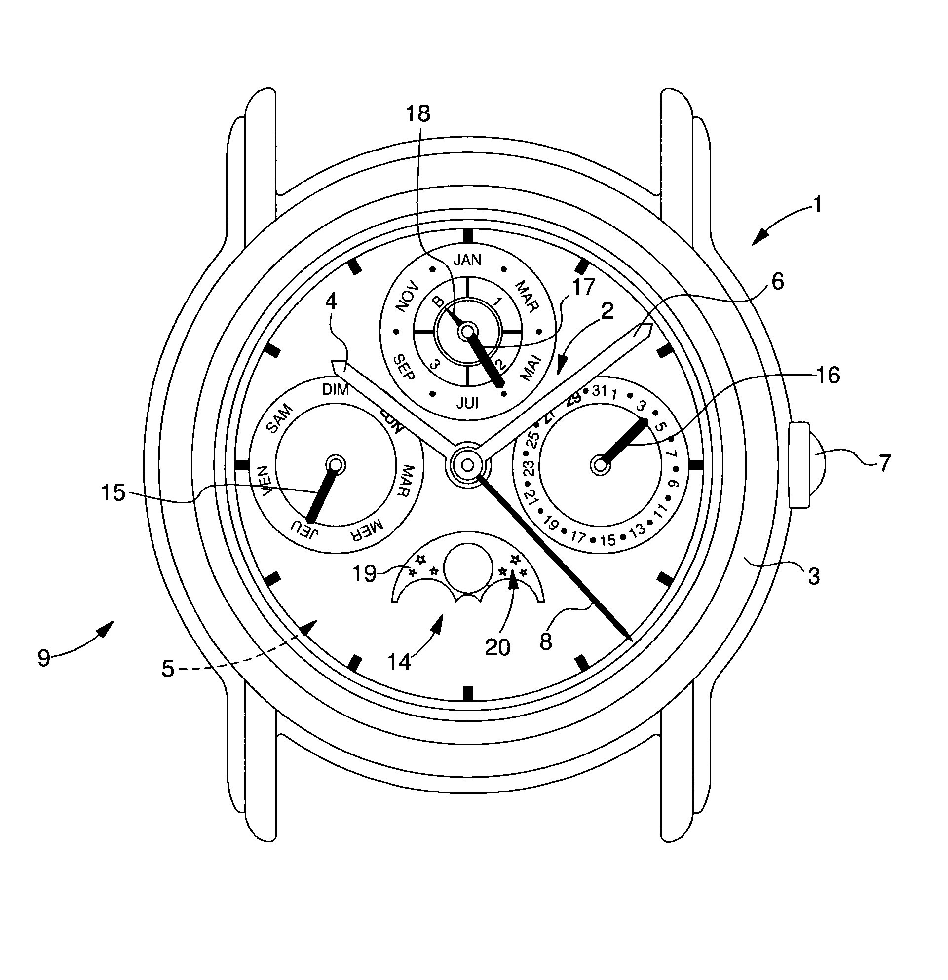
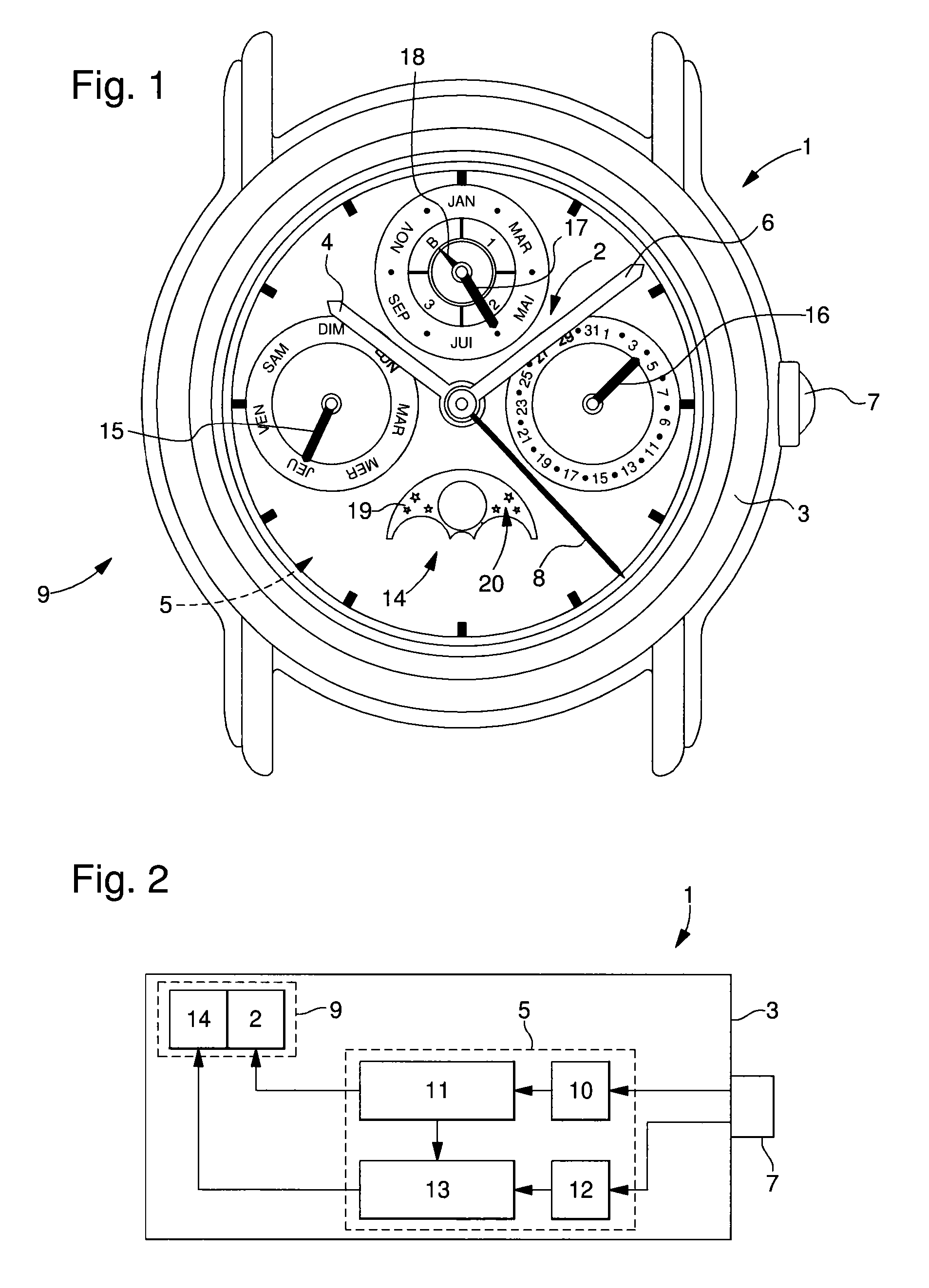
[0023]The example illustrated in FIG. 2 shows a schematic diagram of a mechanical part1 according to the invention. The part includes a case 3 inside which there is mounted a mechanical mechanism 5 controlled by at least one control member 7, which preferably projects from case 3 and is for correcting the display device 9 of timepiece 1.

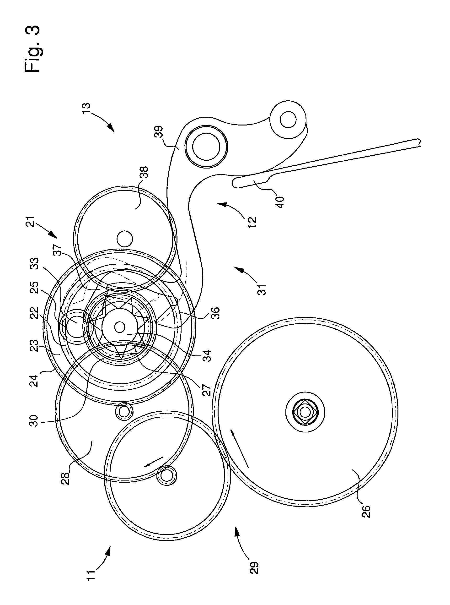
[0024]According to the invention, mechanism 5 including a measuring system 11, 13 is mechanically connected to a display system 9 for displaying a time-related or other piece of information 2, 14. Advantageously according to the invention, the display system 9 includes a quick correction device 10, 12 with an epicycloidal gear train for correcting said time-related or other information display 2, 14 at any time while maintaining the relationship between display system 9 and measuring system 11, 13 during the correction phase.

[0025]By way of example, mechanism 5 may be a timepiece movement 5 which includes a time measuring system 11 for displaying the...


PUM


Abstract

The invention relates to a mechanism (5) comprising a measuring system (11, 13) mechanically connected to a display system (9) for displaying a time-related or other piece of information (2, 14). According to the invention, the display system (9) includes a quick correction device (10, 12) with an epicycloidal gear train for correcting said display of time-related or other information (2, 14) at any time while maintaining the relationship between the display system (9) and the measuring system (11, 13) during the correction phase.The invention particularly concerns the field of timepieces.

Description

[0001]This application claims priority from European Patent Application No. 12150548.1 filed Jan. 10, 2012, the entire disclosure of which is incorporated herein by reference.FIELD OF THE INVENTION[0002]The invention relates to a timepiece comprising a display system and, more specifically, to a system of this type comprising a quick correction device.BACKGROUND OF THE INVENTION[0003]Display systems are widely used in horology. Mechanisms currently used for display are dragging, instantaneous or semi-instantaneous mechanisms. Current mechanisms may make it difficult to correct the display member, such as the calendar, in proximity to the change of the display member and require the use of a safety device to avoid damage. Moreover current correction devices may cause stress in the gear train when the display is corrected.SUMMARY OF THE INVENTION[0004]It is an object of the present invention to overcome all or part of the aforecited drawbacks by proposing a quick correction device whi...

Claims


Application Information

Patent Timeline
Patent Type & Authority Patents(United States)
IPC IPC(8): G04B19/26G04B27/00G04B47/00G04B19/24G04B47/06
CPCG04B19/262G04B19/24G04B19/268G04B27/001G04B27/005G04B47/06G04B47/068G04B47/066
Inventor ZAUGG, ALAIN
Owner MONTRES BREGUET
Learn More