Lateral spondylolisthesis reduction cage

a spondylolisthesis and cage technology, applied in the field of lateral spondylolisthesis reduction cages, can solve the problems of low degree of spondylolisthesis correction, cage malposition, and inability to correct spondylolisthesis, and achieve the effect of correcting spondylolisthesis

Inactive Publication Date: 2014-09-30
DEPUY SYNTHES PROD INC
View PDF204 Cites 76 Cited by
  • Summary
  • Abstract
  • Description
  • Claims
  • Application Information

AI Technical Summary

Benefits of technology

[0036]so that rotation of the pinion effects relative movement of the upper and lower walls in the anterior-posterior direction.

Problems solved by technology

However, correction from the lateral approach is currently limited to regaining height and lordosis with only a low degree of spondylolisthesis correction, as the straight or lordotic cage is impacted during insertion to expand the disc space.
The lack of conformity of the cage endplate to the pertinent vertebral body can promote cage malpositioning during insertion, improper load balancing, increased settling and / or subsidence, as well as device movement following implantation.
However, most currently available lateral cages do not provide for plate attachment.

Method used


Image

  • Lateral spondylolisthesis reduction cage
  • Lateral spondylolisthesis reduction cage
  • Lateral spondylolisthesis reduction cage

Examples


first embodiment

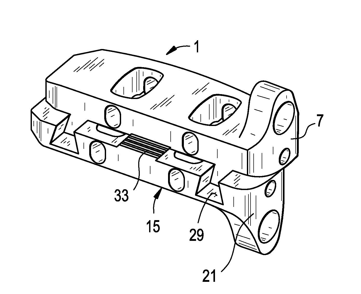
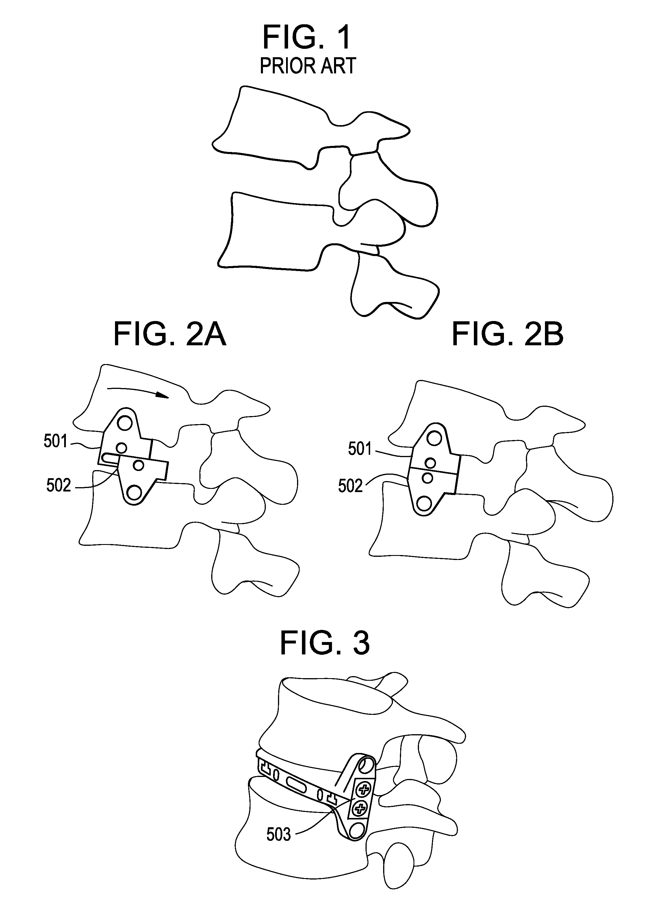
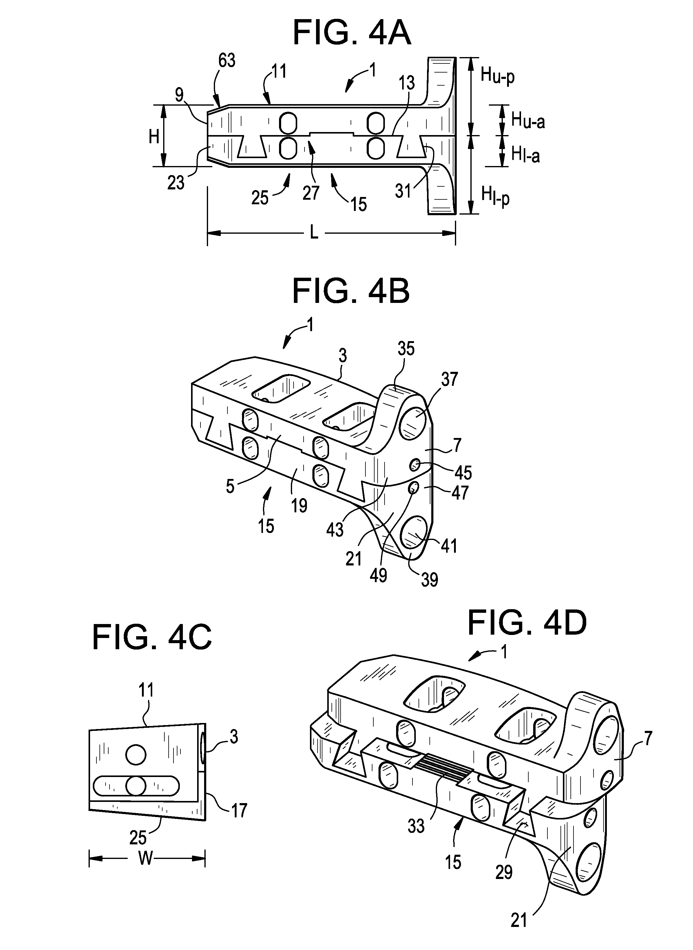
[0058]FIGS. 2a-2b and 3 disclose the implantation of a fusion device of the present invention, in which the cages 501,502 of the device are implanted into the disc space, brought together, and then locked in place with a locking plate 503. FIGS. 4a-4d show various views of the intervertebral fusion device of the present invention. FIGS. 4e-4f show various views of the cages of an intervertebral fusion device of the present invention locked with a locking plate.

[0059]FIG. 2a and FIG. 2b respectively show the relative positions of the fixed cage before and after alignment. In the FIG. 2b position, the cages have properly aligned the vertebral bodies, and thereby corrected the spondylolisthesis. The superior and inferior cages can also have features that provide or enhance the connection of the cages to the compressor. These features include recesses, pilot holes and threads located on the proximal walls of the two cages (and optionally extending therethrough) that receive mating featu...

second embodiment

[0084]In a second embodiment, and now referring to FIG. 8a-8d, the alignment means is rotary spreader-activated. FIGS. 8a-8d disclose how the cages of one embodiment of the present invention are aligned by a rotary spreader, and are locked by a particular locking plate. A modified spreader or shaver can be inserted into a space formed in the proximal end wall of the unaligned device. Rotating the spreader causes relative anterior-posterior movement of the upper cage vis-a-vis the lower cage to enable alignment of the cages and thereby intraoperative adjustment of a spondylosed functional spinal unit (FSU).

[0085]Now referring to FIG. 8b, optional locking plates can be employed to fix the device after the spondylolisthesis has been corrected. These plates are preferably inserted into bilateral, aligned, longitudinal recesses that extend across the interface of the aligned cages to provide inter-cage locking. In some embodiments, these plates are locked into place via a snap-lock mecha...

third embodiment

[0093]In a third embodiment, and now referring to FIGS. 9a-9g, the attachment means is linkage activated. FIGS. 9a-9g disclose various views of a dual linkage embodiment of the present invention Single- or double-linkage can be used to correct spondylolisthesis by moving this cage from a pre-activated (FIG. 9a) to a post-activated state. (FIG. 9b) In some linkage embodiments, the anterior and posterior walls of the cages also function as linkage bars, providing for pivoting connection with both an upper wall component and a lower wall component to allow for relative anterior-posterior movement of the upper wall vis-à-vis the lower wall and thereby spondylolisthesis correction.

[0094]In some embodiments, and now referring to FIGS. 9c-9d, the upper portion of the upper wall and the lower portion of the lower wall extend outwardly, and transverse holes in these portions provide a means to fix the upper and lower walls to the respective lateral walls of the vertebral bodies.

[0095]In some...


PUM


Abstract

An intervertebral fusion device comprising inferior and superior fusion cage devices that provide an ability to correct spondylolisthesis via in-situ adjustment.

Description

CONTINUING DATA[0001]This application claims priority from provisional application U.S. Ser. No. 61 / 397,716, filed Nov. 30, 2010, entitled Lateral Spondylolisthesis Reduction Cage, the specification of which is incorporated by reference in its entirety.[0002]This application claims priority from provisional application U.S. Ser. No. 61 / 358,220, filed Jun. 24, 2010, entitled Instruments and Methods for Non-Parallel Disc Space Preparation, and is related to non-provisional U.S. Ser. No. 13 / 163,471, filed on Jun. 17, 2011, entitled Instruments and Methods for Non-Parallel Disc Space Preparation, the specifications of which are incorporated by reference in their entireties.[0003]This application claims priority from U.S. Ser. No. 61 / 379,194, filed on Sep. 1, 2010, and entitled “Flexible Vertebral Body Shavers”, and is related to non-provisional U.S. Ser. No. 13 / 163,496, filed on Jun. 17, 2011, entitled “Flexible Vertebral Body Shavers”, the specifications of which are incorporated by re...

Claims


Application Information

Patent Timeline
Patent Type & Authority Patents(United States)
IPC IPC(8): A61F2/44A61B5/00A61B17/02A61B17/16A61B17/17A61B17/34A61M25/00A61M25/01A61M29/02
CPCA61M29/02A61B17/1757A61B17/1671A61B17/1659A61M25/0054A61B5/4893A61M25/0133A61B2017/0256A61B2017/3433A61F2/447A61F2/4611A61F2/4455A61F2002/30326A61F2/446A61F2/4465A61F2002/443A61F2/4603A61F2/4425A61F2/30771A61F2/4637A61F2002/30523A61F2002/30593
Inventor O'NEIL, MICHAEL JSERHAN, HASSANRAYMOND, DOUGLASHAWKINS, JOHN RILEY
Owner DEPUY SYNTHES PROD INC
Why Eureka
Try Eureka