
Printing system, printing apparatus, and job processing method

a printing system and printing technology, applied in the direction of digital output to print units, instruments, book binding, etc., can solve the problems of inability to continuously operate without stop, failure to efficiently process a plurality of jobs at high productivity, and long time for printing of many pages

Inactive Publication Date: 2014-09-30
CANON KK
View PDF41 Cites 3 Cited by
  • Summary
  • Abstract
  • Description
  • Claims
  • Application Information

AI Technical Summary

Benefits of technology

[0007]It is an object of the present invention to provide a convenient printing system adaptable not only to the office environment but also to the POD environment, a printing apparatus, and a job processing method.
[0008]It is another object of the present invention to provide a mechanism of minimizing intervention work by an operator that may occur in the POD environment due to the specifications of an image forming apparatus designed in consideration of only the office environment. It is still another object of the present invention to implement efficient work by reducing the workload of the operator.
[0009]It is still another object of the present invention to provide a mechanism capable of flexibly coping with various needs from various users as much as possible in consideration of various situations and use environments.
[0010]It is still another object of the present invention to provide a mechanism of increasing the productivity of a printing system by automatically executing print processing in a proper operation mode.

Problems solved by technology

In printing, the printer engine cannot continuously operate without stop depending on the printing environment, failing to efficiently process a plurality of jobs at high productivity.
To the contrary, even when the printing apparatus can execute an operation mode in which print processing by the printer engine starts after the end of all rasterization processing, printing of many pages takes a long time until all pages are printed.

Method used


Image

  • Printing system, printing apparatus, and job processing method
  • Printing system, printing apparatus, and job processing method
  • Printing system, printing apparatus, and job processing method

Examples


Embodiment Construction

[0031]The best mode for carrying out the present invention will be explained in detail below with reference to the accompanying drawings.

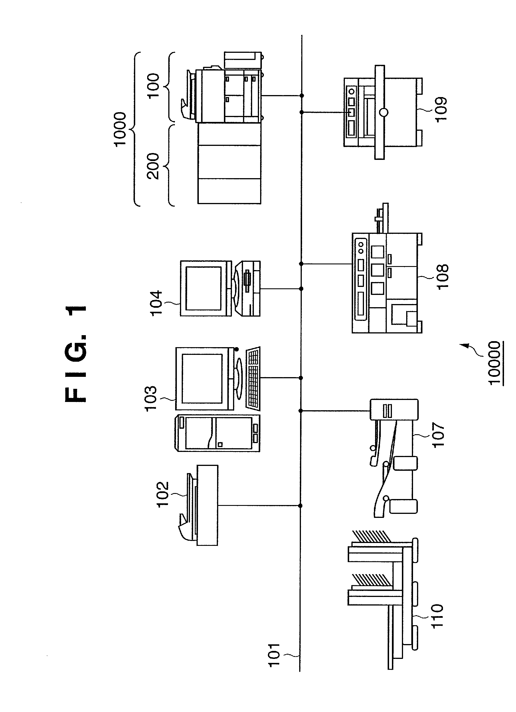
[0032]A POD system 10000 in FIG. 1 comprises a printing system 1000, scanner 102, server computer (PC) 103, and client computer (PC) 104, which are connected to each other via a network 101. Sheet processing apparatuses such as a paper folding apparatus 107, case binding apparatus 108, cutting apparatus 109, and saddle stitching apparatus 110 are also connected to the POD system 10000.

[0033]The printing system 1000 comprises a printing apparatus 100 and sheet processing apparatus 200. As an example of the printing apparatus 100, the embodiment will describe an MFP (Multi Function Peripheral) having a plurality of functions such as the copy and printer functions. However, the printing apparatus 100 may be a single function type printing apparatus having only the copy or printer function.

[0034]The server computer (PC) 103 manages data exchange with a...


PUM


Abstract

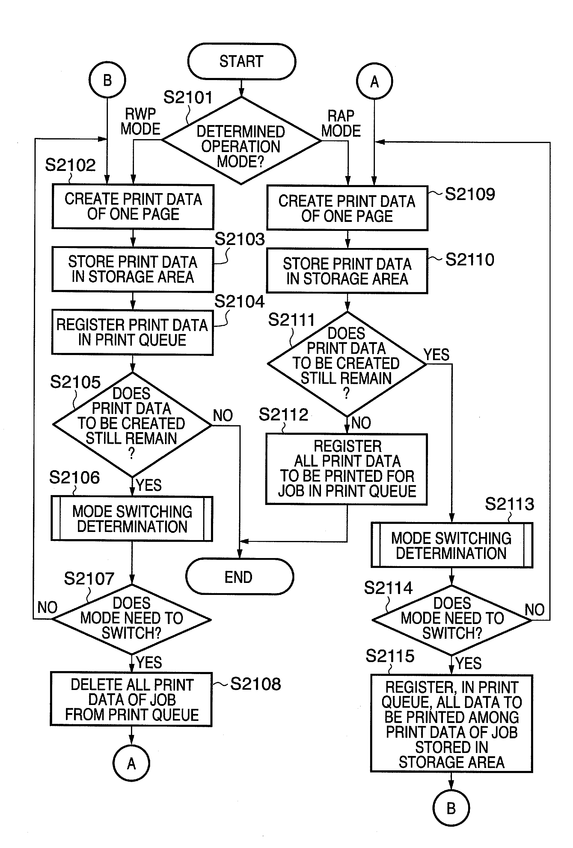
A printing system has the first operation mode in which printing starts during processing of a target job, and the second operation mode in which printing starts upon completion of processing of the job. It is determined on the basis of the processing status of the job in the printing system whether to switch the operation mode to the first or second operation mode. The operation mode is controlled to switch between the first and second operation modes in accordance with the determination result.

Description

BACKGROUND OF THE INVENTION[0001]1. Field of the Invention[0002]The present invention relates to a printing system adapted to be able to execute first and second operations, a printing apparatus, and a job processing method.[0003]2. Description of the Related Art[0004]Recently, a POD (Print On Demand) printing system using an electrophotographic or inkjet printing apparatus has been proposed (see, e.g., patent reference 1: Japanese Patent Laid-Open No. 2004-310746, and patent reference 2: Japanese Patent Laid-Open No. 2004-310747).[0005]In the POD environment, a printing apparatus receives PDL data or PDF file data to be printed from an external apparatus, and rasterizes the data into a bitmap image (raster image data) to be printed on the basis of the result of analyzing the data. The printer engine prints the rasterized bitmap image. In printing, the printer engine cannot continuously operate without stop depending on the printing environment, failing to efficiently process a plur...

Claims


Application Information

Patent Timeline
Patent Type & Authority Patents(United States)
IPC IPC(8): G06F15/00B42B4/00B42C9/00
CPCB42B4/00B42C9/0031
Inventor SHIMADA, BUNGO
Owner CANON KK
Learn More