Printing system and control method therefor

a printing system and control method technology, applied in the field of printing systems, can solve problems such as failure to complete outpu

Inactive Publication Date: 2008-02-21
CANON KK
View PDF26 Cites 24 Cited by
  • Summary
  • Abstract
  • Description
  • Claims
  • Application Information

AI Technical Summary

Benefits of technology

[0009]Moreover, the present invention provides a mechanism of minimizing intervention work by an operator that may occur in the POD environment due to the specifications of an image forming apparatus designed in consideration of only the office environment. It is possible to implement efficient work by reducing the work-load of the operator.
[0010]Furthermore, the present invention to provide a mechanism capable of flexibly coping with various needs from various users as much as possible in consideration of various situations and use environments.

Problems solved by technology

However, before a printing apparatus connected to a plurality of large-volume stackers completes printing of a job accompanied by output of many pages, one large-volume stacker may become fully loaded with output materials, failing to complete the output.

Method used


Image

  • Printing system and control method therefor
  • Printing system and control method therefor
  • Printing system and control method therefor

Examples


example 1

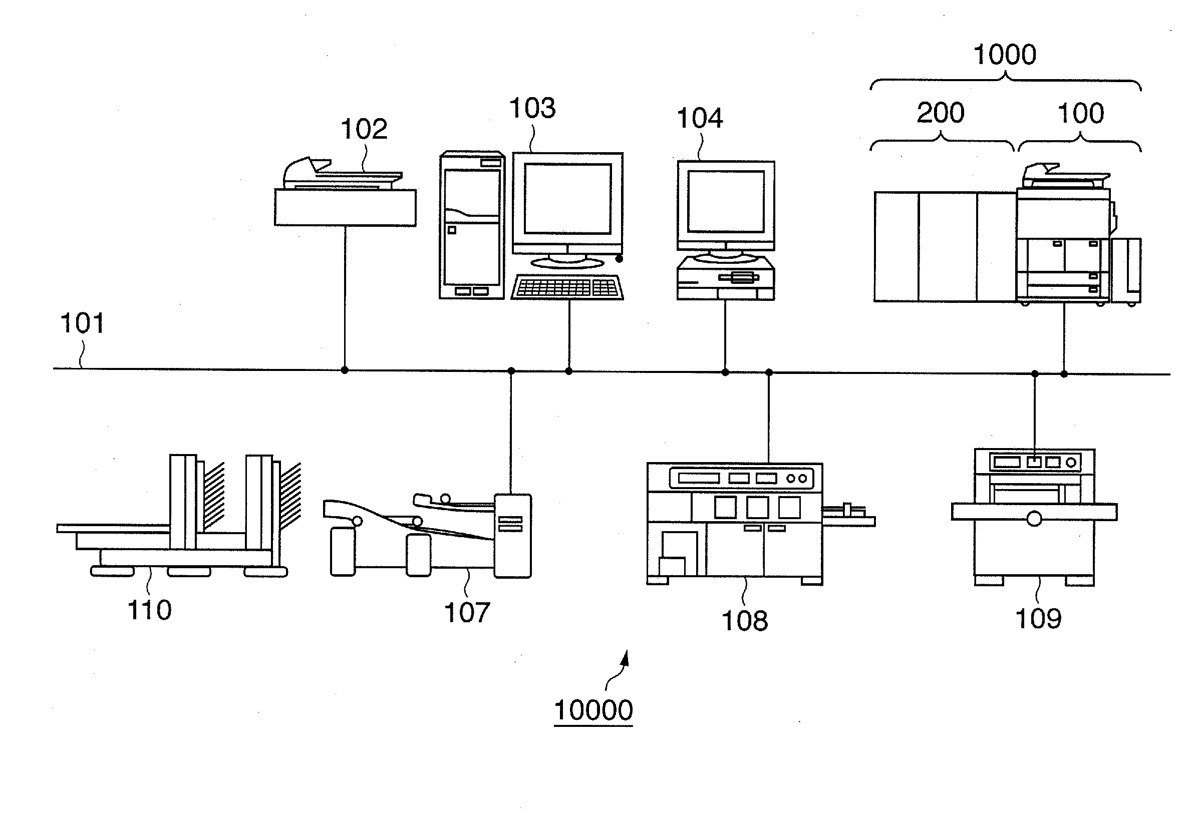
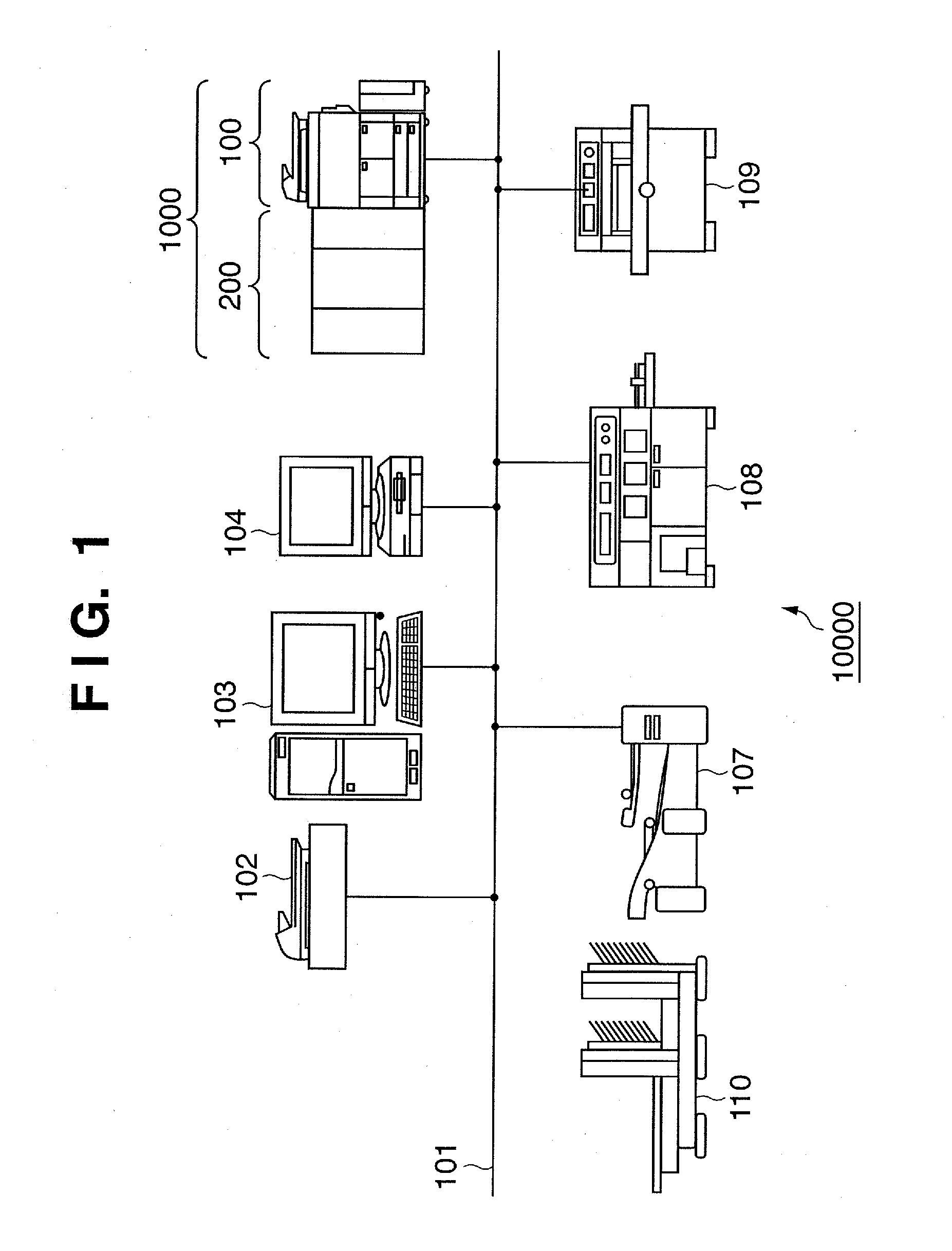
[0106]A case where the user registers, in the setup window shown in FIG. 9, a configuration in which a large-volume stacker and saddle stitching apparatus are connected to the printing apparatus 100 will be exemplified.

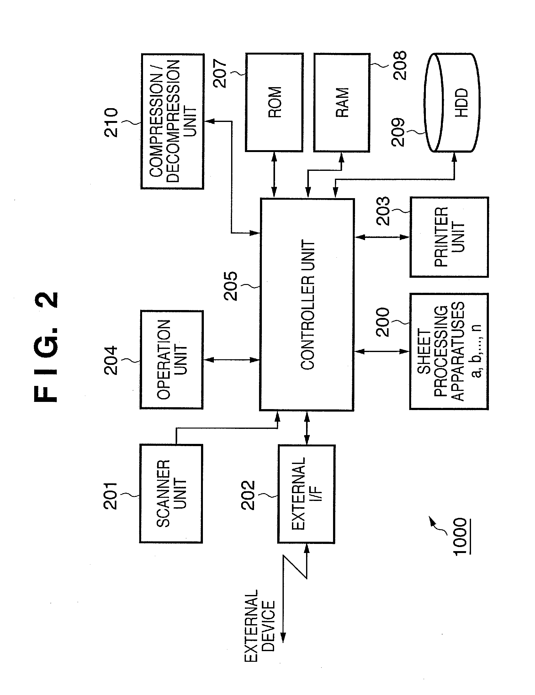
[0107]When the user presses the user mode key 505 of the operation unit 204, regardless of whether printing of a job is in progress, the control unit 205 of the printing apparatus 100 controls the operation unit 204 to display an operation window 2100 in FIG. 11 for a configuration in which a plurality of sheet processing apparatuses are connected. In the operation window 2100, each key 2101 is used to set the operation of the printing apparatus. The operation window 2100 displays a name 2102 of each operation setting item and a setting value 2103 of each operation setting item. When the user presses a close key 2104, the control unit 205 detects that the user has pressed the close key 2104, closes the window 2100, and displays a copy operation window.

[0108]When the u...

example 2

[0118]A case where the user registers, in the setup window shown in FIG. 9, a configuration in which two large-volume stackers and a saddle stitching apparatus are connected to the printing apparatus 100 will be exemplified. In this configuration, a large-volume stacker is connected instead of the glue binding apparatus 200b shown in FIG. 3, and two large-volume stackers are successively cascade (tandem)-connected. The second large-volume stacker will be referred to as a “large-volume stacker 200b”. The type and number of connected sheet processing apparatuses are not limited to this example.

[0119]An operation window which exemplifies the copy function will be described. In copying, the control unit 205 displays a sheet processing type selection window 700 shown in FIG. 8. When the control unit 205 detects that the user has pressed the large-volume stacking key 709, it displays an operation window 2400 shown in FIG. 14. The operation window 2400 has a delivery destination key 2401 f...

example 3

[0154]Still another control method for printing control of a sheet processing apparatus preparing for large-volume printing described in examples 1 and 2 will be explained.

[0155]When alternate output in stacker output=OFF in example 1, or the stack tray of the large-volume stacker is fully loaded in example 2, the control unit 205 controls to stop output of a print job until the full load state is canceled. Still another example will be described below.

[0156]When the control unit 205 detects that alternate output in stacker output=OFF in example 1, or the stack tray of the large-volume stacker becomes fully loaded in example 2, it popup-displays an operation window 2600 illustrated in FIG. 21 on the touch panel unit 401. That is, the control unit 205 popup-displays the operation window 2600 on the touch panel unit 401 upon detecting the full load state in S2304 in example 1, determining tandem=OFF in S2507 in example 2, or detecting the full load state in S2509. Since the stack tray...


PUM

PropertyMeasurementUnit
volumeaaaaaaaaaa
internal structureaaaaaaaaaa
structureaaaaaaaaaa

Abstract

A printing system adapted to be able to supply printed materials from a printing apparatus to a first stacking unit of a first sheet processing apparatus and a second stacking unit of a second sheet processing apparatus, the system comprising a receiver and controller, the receiver receiving via a user interface unit a specified instruction that allows the printing system to perform a first type operation, the first type operation being an operation that both the first stacking unit and the second stacking unit can be used in printing of a job to be processed, the controller causing the printing apparatus to perform the first type operation in a case where the specified instruction is received, the controller causing the printing apparatus to perform a second type operation in a case where the specified instruction is not received, the second type operation being an operation that one of the first stacking unit and the second stacking unit can be used in printing of a job to be processed.

Description

BACKGROUND OF THE INVENTION[0001]1. Field of the Invention[0002]The present invention relates to a printing system adapted to be able to supply materials printed by a printing apparatus to either the destination of the first sheet processing apparatus or that of the second sheet processing apparatus, and a control method therefor.[0003]2. Description of the Related Art[0004]Recently, a POD (Print On Demand) printing system using an electrophotographic or inkjet printing apparatus has been proposed (see, e.g., patent reference 1: Japanese Patent Laid-Open No. 2004-310746, and patent reference 2: Japanese Patent Laid-Open No. 2004-310747).[0005]In the POD environment, there is a dolly-attached sheet processing apparatus also called a large-volume stacker which outputs many printed materials and assumes the use of a sheet processing apparatus. There are also prepared a printing apparatus capable of connecting a plurality of large-volume stackers, and a printing apparatus connected to e...

Claims


Application Information

Patent Timeline
Patent Type & Authority Applications(United States)
IPC IPC(8): B65H29/00
CPCB65H39/10B65H2301/16B65H2511/414B65H2513/42B65H2551/00B65H2801/15B65H2220/01B65H2220/02B65H7/20B65H31/24B65H37/00B65H43/00
Inventor TOMINAGA, MASAHIKOMAEDA, YUUKI
Owner CANON KK
Why Eureka
Try Eureka