
Radio base station and communication control method

a technology of communication control and radio base station, which is applied in the direction of signal characterisation, wireless communication, transmission path sub-channel allocation, etc., can solve the problems of difficult for pdcch to receive interference from other cells or other sectors, low quality of pdcch, and high cost, and achieves suitable estimation

Active Publication Date: 2014-09-30
KYOCERA CORP
View PDF9 Cites 0 Cited by
  • Summary
  • Abstract
  • Description
  • Claims
  • Application Information

AI Technical Summary

Benefits of technology

This approach enables more accurate estimation of PDCCH quality, reducing unnecessary resource usage and improving communication efficiency by aligning PDCCH settings with actual conditions, thus enhancing overall system performance.

Problems solved by technology

However use of this type of operation may entail the problem of interference to a given cell or sector from other cell or other sector.
However, based on the LTE standard, a radio terminal transmits only the quality of PDSCH to a radio base station, and does not transmit the quality of PDCCH.
However, generally, the utilization ratio of a radio resource of PDCCH is lower than the utilization ratio of a radio resource of PDSCH, and therefore, as compared to PDSCH, it is difficult for PDCCH to receive interference from other cell or other sector.
Therefore, if the quality of PDSCH is assumed to be the quality of PDCCH, the quality of PDCCH would be estimated to be extremely low, giving rise to a problem that the number of repetitions of transmission of the same information would increase and more than the required number of radio resources would be used.

Method used


Image

  • Radio base station and communication control method
  • Radio base station and communication control method
  • Radio base station and communication control method

Examples


Embodiment Construction

[0035]Next, an embodiment of the present invention will be described with reference to the drawings. More specifically, (1) Configuration of Radio Communication System, (2) Operation of Radio Base Station, (3) Operation and Effect, and (4) Other Embodiments will be described. It is to be noted that the same or similar reference numerals are applied to the same or similar parts through the drawings in the following embodiments.

(1) Configuration Of Radio Communication System

(1.1) Entire Schematic Configuration of Radio Communication System

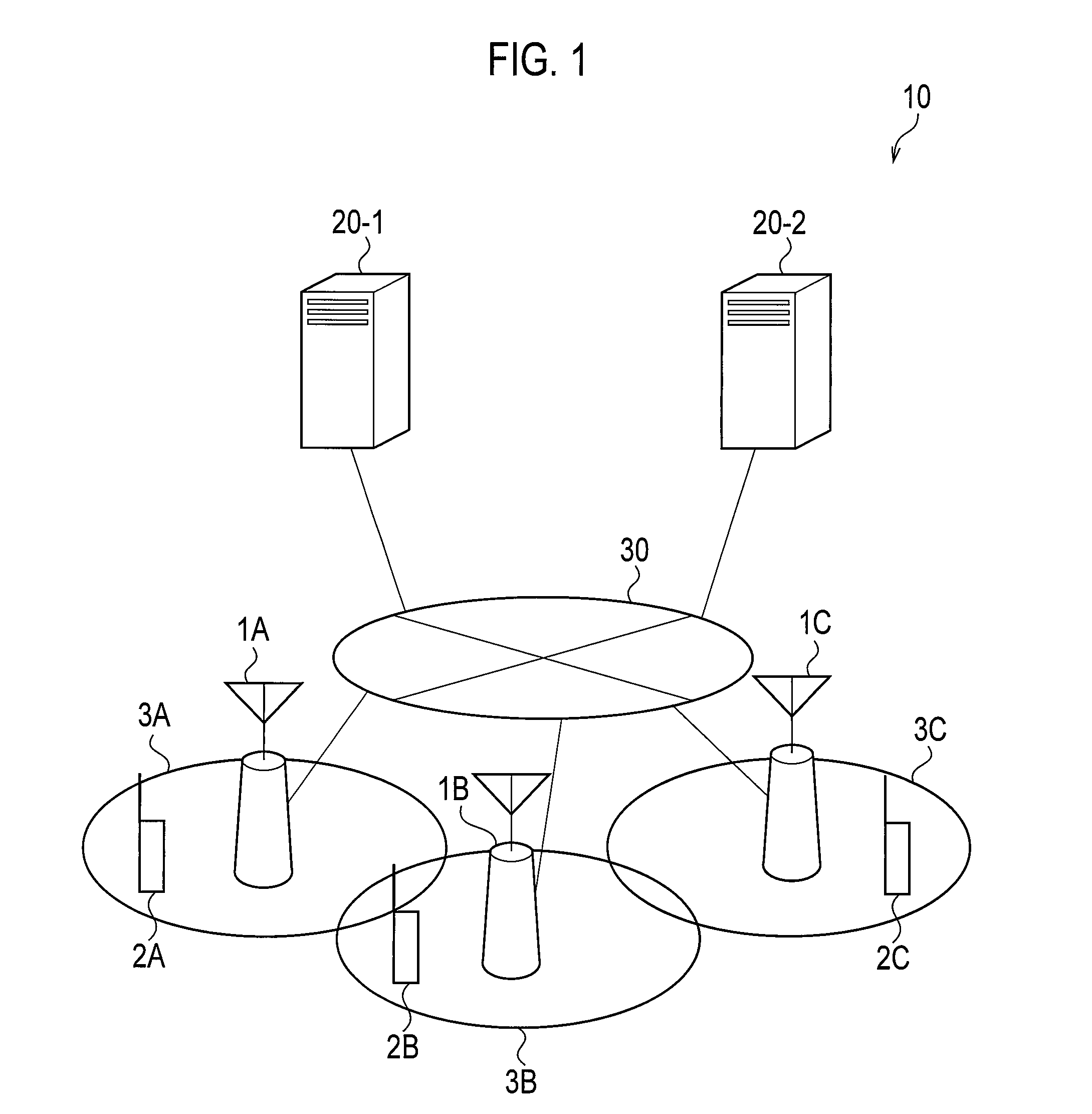
[0036]FIG. 1 is a diagram showing the entire schematic configuration of a radio communication system 10 according to an embodiment of the present invention.

[0037]The radio communication system 10 illustrated in FIG. 1 has a configuration based on LTE (Long Term Evolution) which is a standard designed in 3GPP. The radio communication system 10 includes a radio base station 1A, a radio base station 1B, a radio base station 1C, a radio terminal 2A, a ra...


PUM


Abstract

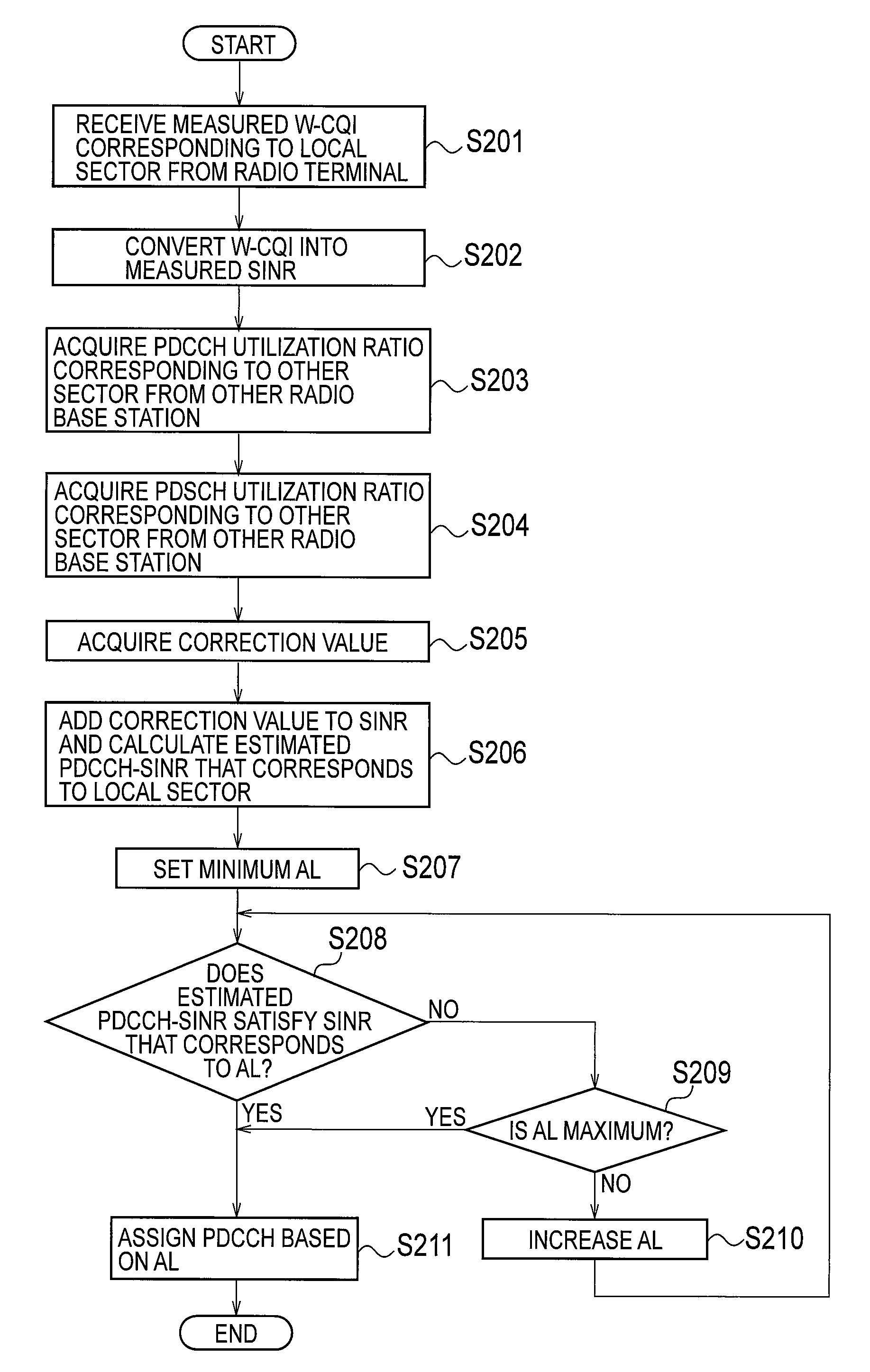
A control unit (102) in a radio base station (1A) receives from a radio terminal (2A) a measured W-CQI corresponding to a local sector, and also acquires the utilization ratio of a PDCCH corresponding to the sector. Also, in addition to receiving a measured W-CQI corresponding to the local sector, the control unit (102) in the radio base station (1A) acquires from other radio base stations (1B and 1C) utilization ratios of PDCCHs and PDSCHs corresponding to other sectors. Additionally, the control unit (102) in the radio base station (1A) estimates the PDCCH quality (SINR) corresponding to the local sector on the basis of a SINR obtained from the measured W-CQIs and also on the basis of the utilization ratios of PDCCHs and PDSCHs corresponding to other sectors.

Description

TECHNICAL FIELD[0001]The present invention relates to a radio base station configured such that a radio resource corresponding to a predetermined cell or sector is configured by a radio resource for transmitting control information and a radio resource for transmitting user data, the radio resource is assigned to a radio terminal, and communication is performed with the radio terminal, and relates also to a communication control method of the radio base station.BACKGROUND ART[0002]In recent years, ongoing increase to capacity and speed is required in response to implementation of broadband to mobile communication services. In this regard, a 3rd-generation mobile communication system represented by W-CDMA (Wideband Code Division Multiple Access) or the next-generation mobile communication system, which is an alternative to a 3.5th-generation mobile communication system, has been commercialized all over the world. Also in Japan, frequency assignment to a 3.9th-generation mobile commun...

Claims


Application Information

Patent Timeline
Patent Type & Authority Patents(United States)
IPC IPC(8): H04W72/04H04W72/54H04L1/00H04L5/00H04W88/08
CPCH04W72/082H04L5/006H04L1/0026H04L5/0044H04L1/0029H04L5/0053H04W88/08H04W72/541
Inventor NAKAYAMA, TAKU
Owner KYOCERA CORP
Learn More