
Fuel cell vehicle and liquid state estimation method

a fuel cell and liquid state technology, applied in the direction of battery/fuel cell control arrangement, electrochemical generators, battery/cell propulsion, etc., can solve the problems of increasing the size of the apparatus, reducing the production cost disadvantageously, and not achieving sufficient size reduction, so as to reduce the volume of the portion, reduce the size of the gas liquid separation unit, and reduce the production cost

Active Publication Date: 2022-08-02
HONDA MOTOR CO LTD
View PDF5 Cites 0 Cited by
  • Summary
  • Abstract
  • Description
  • Claims
  • Application Information

AI Technical Summary

Benefits of technology

The present invention aims to provide a fuel cell vehicle and a liquid state estimation method that can appropriately determine the state of liquid in a gas liquid separation unit, and take suitable measures accordingly. By using information regarding acceleration, the method can determine if the liquid is being discharged or remains as the remaining liquid inside the gas liquid separation unit. This enables the reduction of the size of the gas liquid separation unit and cost production.

Problems solved by technology

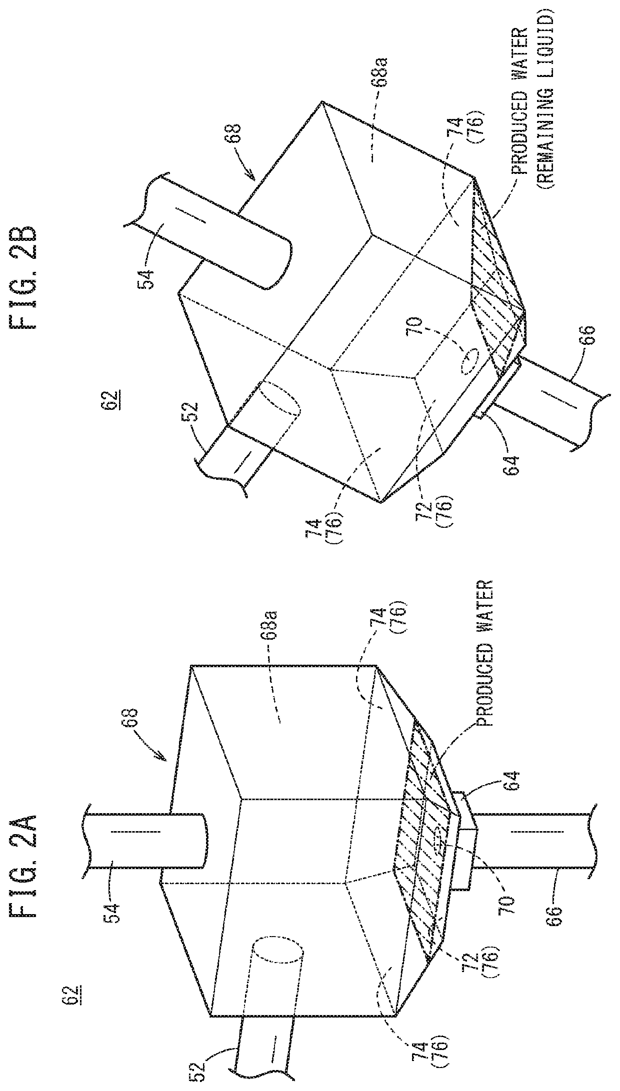
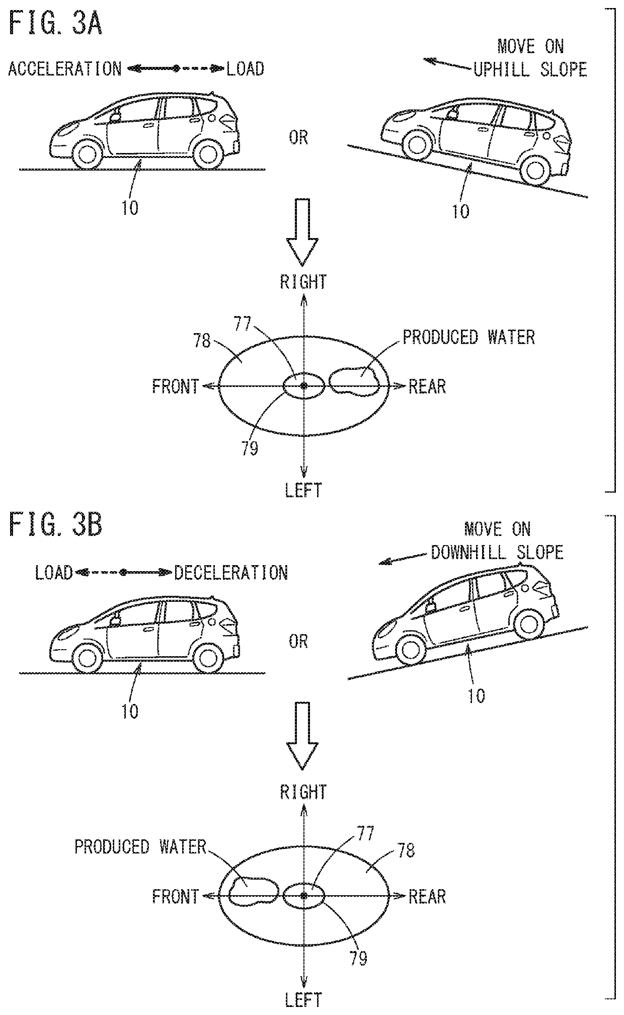
Therefore, even if a purge valve is placed in the open state, the liquid stored in a gas liquid separation unit is affected by the orientation and acceleration of the vehicle, the liquid may move to a position remote from the opening, and may not be discharged from the gas liquid separation unit.
For this reason, in general, the gas liquid separation unit is configured to store the remaining liquid until the next drainage timing, which results in increase in the size of the apparatus.
Consequently, for example, the degree of freedom in the design is constrained, sufficient reduction in the size is not achieved, and the production cost is pushed up disadvantageously.

Method used


Image

  • Fuel cell vehicle and liquid state estimation method
  • Fuel cell vehicle and liquid state estimation method
  • Fuel cell vehicle and liquid state estimation method

Examples


Embodiment Construction

[0018]Hereinafter, a preferred embodiment of the present invention will be described in detail with reference to the accompanying drawings.

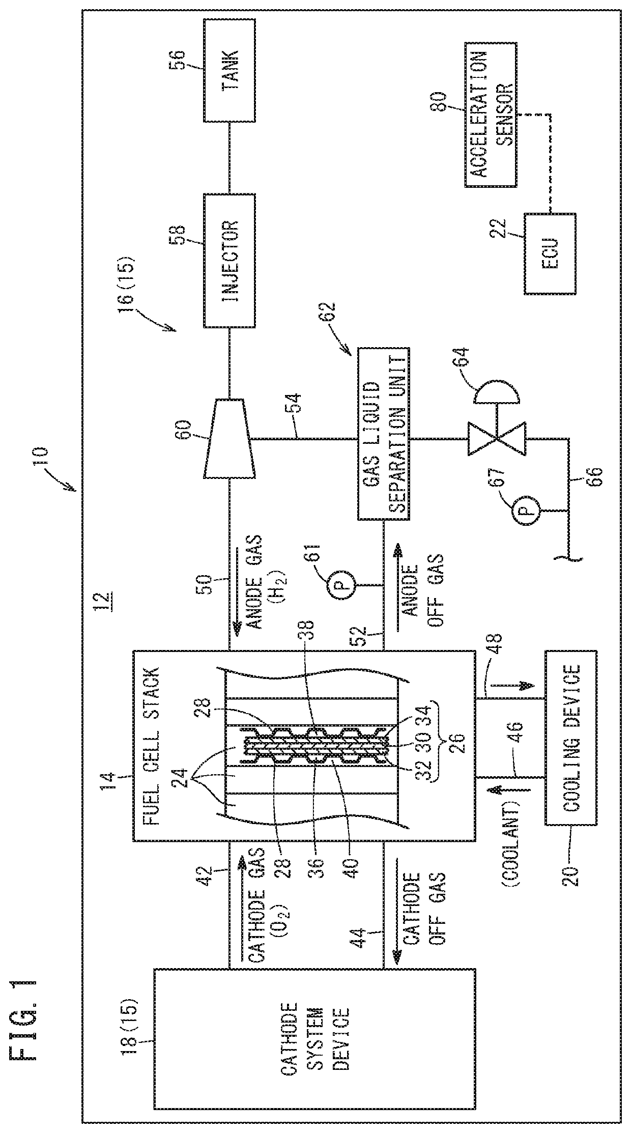
[0019]As shown in FIG. 1, a fuel cell vehicle 10 (fuel cell automobile: hereinafter, simply referred to as the vehicle 10) according to the embodiment of the present invention travels by rotary driving a power source such as a motor based on power generation of a fuel cell system 12. The fuel cell system 12 mounted in the vehicle 10 includes a fuel cell stack 14, reactant gas system devices 15 (an anode system device 16, a cathode system device 18), a cooling device 20, and a control unit 22 (ECU: Electronic Control unit).

[0020]The fuel cell stack 14 includes a plurality of power generation cells 24 which perform power generation by electrochemical reactions of an anode gas (fuel gas such as a hydrogen-containing gas) supplied from the anode system device 16, and a cathode gas (oxygen-containing gas such as the air) supplied from the cathode syst...


PUM

PropertyMeasurementUnit
accelerationaaaaaaaaaa
forceaaaaaaaaaa
acceleration forceaaaaaaaaaa

Abstract

A fuel cell vehicle is equipped with a fuel cell system including a gas liquid separation unit for separating gas and liquid and discharging the separated liquid. The fuel cell vehicle includes an acceleration sensor for detecting information regarding acceleration, and a control unit for estimating the discharge state of the liquid from the gas liquid separation unit based on the information regarding acceleration. Based on acceleration applied to the liquid in the gas liquid separation unit, the control unit can estimate whether the liquid is discharged from the gas liquid separation unit or the liquid is not discharged and remains as the remaining liquid in the gas liquid separation unit.

Description

CROSS-REFERENCE TO RELATED APPLICATION[0001]This application is based upon and claims the benefit of priority from Japanese Patent Application No. 2019-088925 filed on May 9, 2019, the contents of which are incorporated herein by reference.BACKGROUND OF THE INVENTIONField of the Invention[0002]The present invention relates to a fuel cell vehicle equipped with a fuel cell system, and a liquid state estimation method of estimating the discharge state of liquid from a gas liquid separation unit of the fuel cell system.Description of the Related Art[0003]A fuel cell vehicle (fuel cell automobile) is equipped with a gas liquid separator that separates liquid (water produced in power generation (hereinafter simply referred to as the produced water)) contained in reactant gases of a fuel cell system, from the reaction gases. For example, a gas liquid separator disclosed in Japanese Laid-Open Patent Publication No. 2009-231073 stores liquid on the lower side of a case, and discharges the li...

Claims


Application Information

Patent Timeline
Patent Type & Authority Patents(United States)
IPC IPC(8): B60L58/30B60L50/72H01M8/04119
CPCB60L58/30B60L50/72H01M8/04164H01M8/04179H01M2250/20H01M8/04156B60L2240/14H01M2008/1095H01M8/04514H01M8/04843B60L50/70B60L2240/16
Inventor OKAMURA, YUJIFUKUDA, TETSUYA
Owner HONDA MOTOR CO LTD
Learn More