Rotatable grip actuator

a technology of rotating grip and actuator, which is applied in the direction of linear shaft movement, steering device, cycle control system, etc., can solve the problems of the size of injection moulding machine used for the production of shifters, and achieve the effect of reducing friction, ensuring accuracy, and producing simpl

Active Publication Date: 2014-10-07
SRAM
View PDF18 Cites 3 Cited by
  • Summary
  • Abstract
  • Description
  • Claims
  • Application Information

AI Technical Summary

Benefits of technology

[0006]Moreover, the arrangement of ball bearings between the mounting tube and the twist-grip in the axial region, where the spool for winding of the cable to be actuated is located, is a measure for minimising friction.
[0007]A further object is that the parts belonging to the device according to the invention can be produced simply and cost-effectively.

Problems solved by technology

This places corresponding demands on the size of injection moulding machines used for the production of the shifter, which is a disadvantage.

Method used


Image

  • Rotatable grip actuator
  • Rotatable grip actuator
  • Rotatable grip actuator

Examples


Embodiment Construction

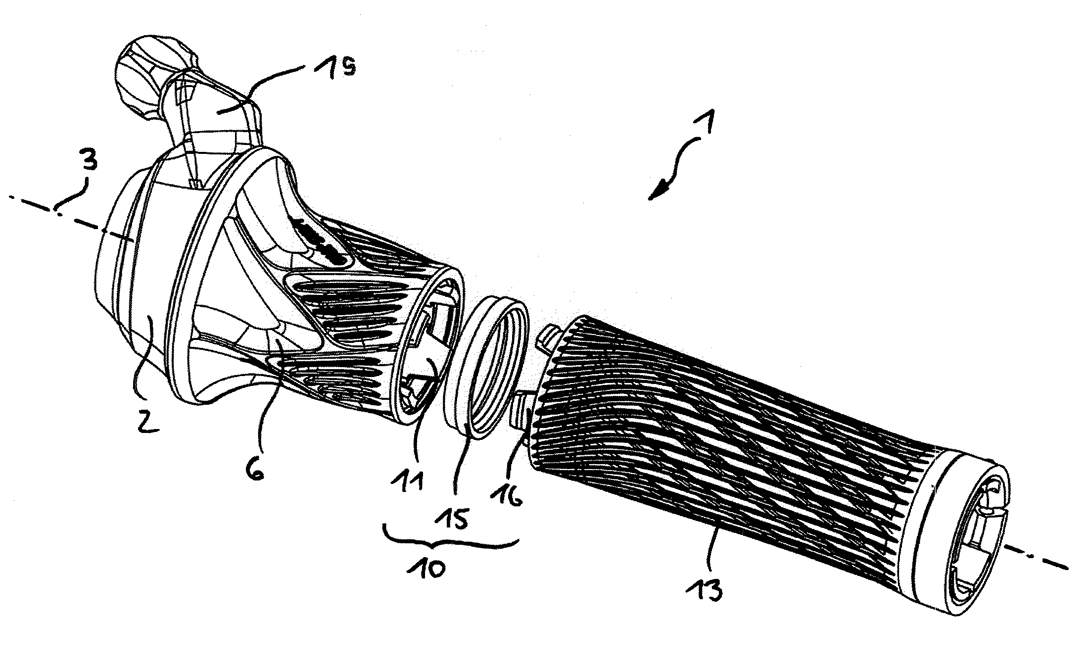
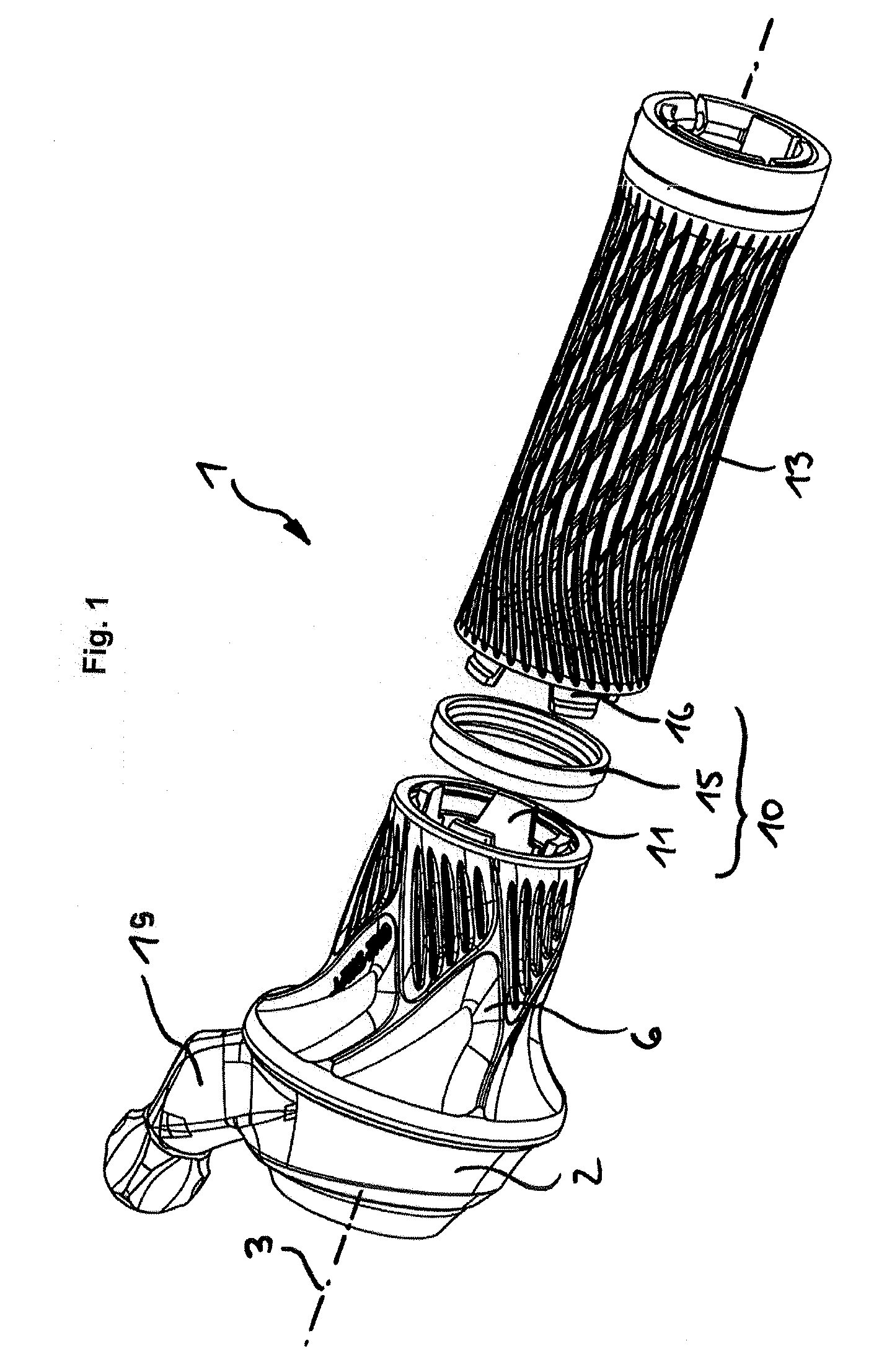
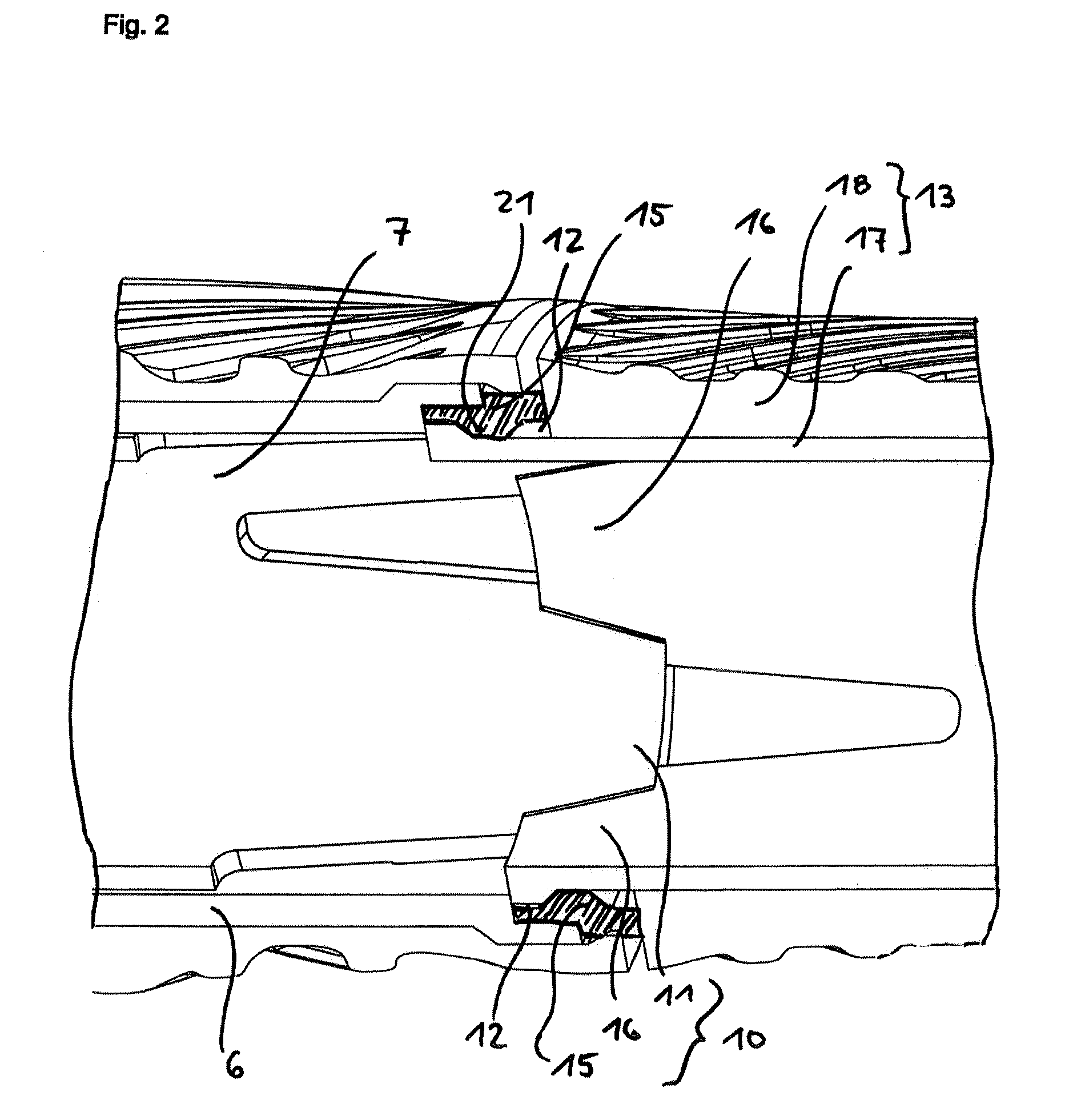
[0016]FIG. 1 is a twist-grip shifter 1 according to an embodiment of the invention for actuation of a cable 5 (see FIG. 5) for shifting between individual gears in a gear shift device on a bicycle. The twist-grip shifter 1 is provided with a connector 10 between a shifter component with a shifter housing 2 and a rotatable handgrip 6 on the one hand and a fixed handgrip 13 on the other hand. The rotatable handgrip part 6 is disposed so as to be rotatable relative to a central or shifter mounting tube 7 (see FIG. 2). The twist-grip shifter 1 is usually fitted on a handlebar, as is well known, which handlebar exteriorly receives the central mounting tube 7.

[0017]A twist-grip shifter 1 according to the invention can be seen in FIGS. 1 and 4. The shifter housing 2 accommodates the mechanism for pulling and releasing a cable 5, which is wound or unwound from a take-up spool 4. In order that after completion of pulling or releasing operations the cable 5 remains positioned in one of the po...


PUM


Abstract

The invention relates to a bicycle twist-grip shifter, which is connectable to a fixed handgrip and is mountable as a structural unit on a handlebar. In this way the fixed handgrip is securely fixed on the handlebar. Moreover, the individual components have an advantageous size for production in an injection molding process. The twist-grip shifter gives the operator a precise operation by avoiding disruptive frictional effects of the rotatable handgrip part on the mounting tube, for which purpose ball bearings are used for bearing the take-up spool, and a metallic positioning ring is used in the positioning mechanism.

Description

BACKGROUND OF THE INVENTION[0001]The present invention relates to a rotatable grip actuator, or as more commonly known, a twist-grip shifter for shifting of bicycle gear units, such as multi-speed hubs or derailleurs.[0002]EP 0 700 827 discloses a twist-grip shifter for controlling bicycle gear units. This twist-grip shifter includes a shifter housing with a shift mechanism, a clamping device for fixing the shifter on the handlebar, a rotatable take-up spool, a mounting tube on which a twist-grip part is rotatably mounted, and a grip end piece seated non-rotatably on the handlebar. The separate grip end piece is generally an elastomeric tube which is frictionally mounted on the handlebar and primarily transmits the manual supporting forces to the handlebar and, unlike twist-grip shifters without an additional fixed handgrip part, prevents unintentional shifting operations. In order to reduce friction, a plastic intermediate ring can be disposed between the twist-grip part and the fi...

Claims


Application Information

Patent Timeline
Patent Type & Authority Patents(United States)
IPC IPC(8): F16C1/10B62K21/12B62K21/26B62K23/04
CPCB62K23/04B62K21/125B62K21/26Y10T74/20438Y10T74/20043
Inventor WEISS, MARTIN
Owner SRAM
Why Eureka
Try Eureka