
Sub frame structure of automotive vehicle

a sub frame and vehicle technology, applied in the direction of vehicle components, pivoted suspension arms, resilient suspensions, etc., can solve the problems of inability to obtain light weight of sub frames, inferior light weight, etc., and achieve the effect of supporting rigidity of suspension links and superior light weigh

Inactive Publication Date: 2014-10-14
MAZDA MOTOR CORP
View PDF11 Cites 17 Cited by
  • Summary
  • Abstract
  • Description
  • Claims
  • Application Information

AI Technical Summary

Benefits of technology

The present invention provides a sub frame structure for automotive vehicles that is light-weight and provides support rigidity for the suspension links. This is achieved by receiving and transmitting external forces from the wheel via the closest link to the wheel center to the attachment portion of the high-rigidity interconnection between the side member and front cross member. Another aspect of the invention is to have a triangular-shaped connecting bracket for proper light-weighting. Additionally, the front cross member, rear cross member, and side members are directly connected to the rear frames without the use of a resilient member, increasing the strength of the connection. The sub frame structure can also be used for open car types of automotive vehicles to improve rigidity in the vehicle body rear portion.

Problems solved by technology

The structure disclosed in the above-described patent document is superior in the rigidity improvement, but inferior in the light weight because of the brace member additionally provided as a reinforcing member.
Accordingly, if each of the attachment portions for the suspension links is reinforced, the light weight of the sub frame may not be obtained.

Method used


Image

  • Sub frame structure of automotive vehicle
  • Sub frame structure of automotive vehicle
  • Sub frame structure of automotive vehicle

Examples


Embodiment Construction

[0037]Hereinafter, a preferred embodiment of the present invention will be described specifically referring to the accompanying drawings.

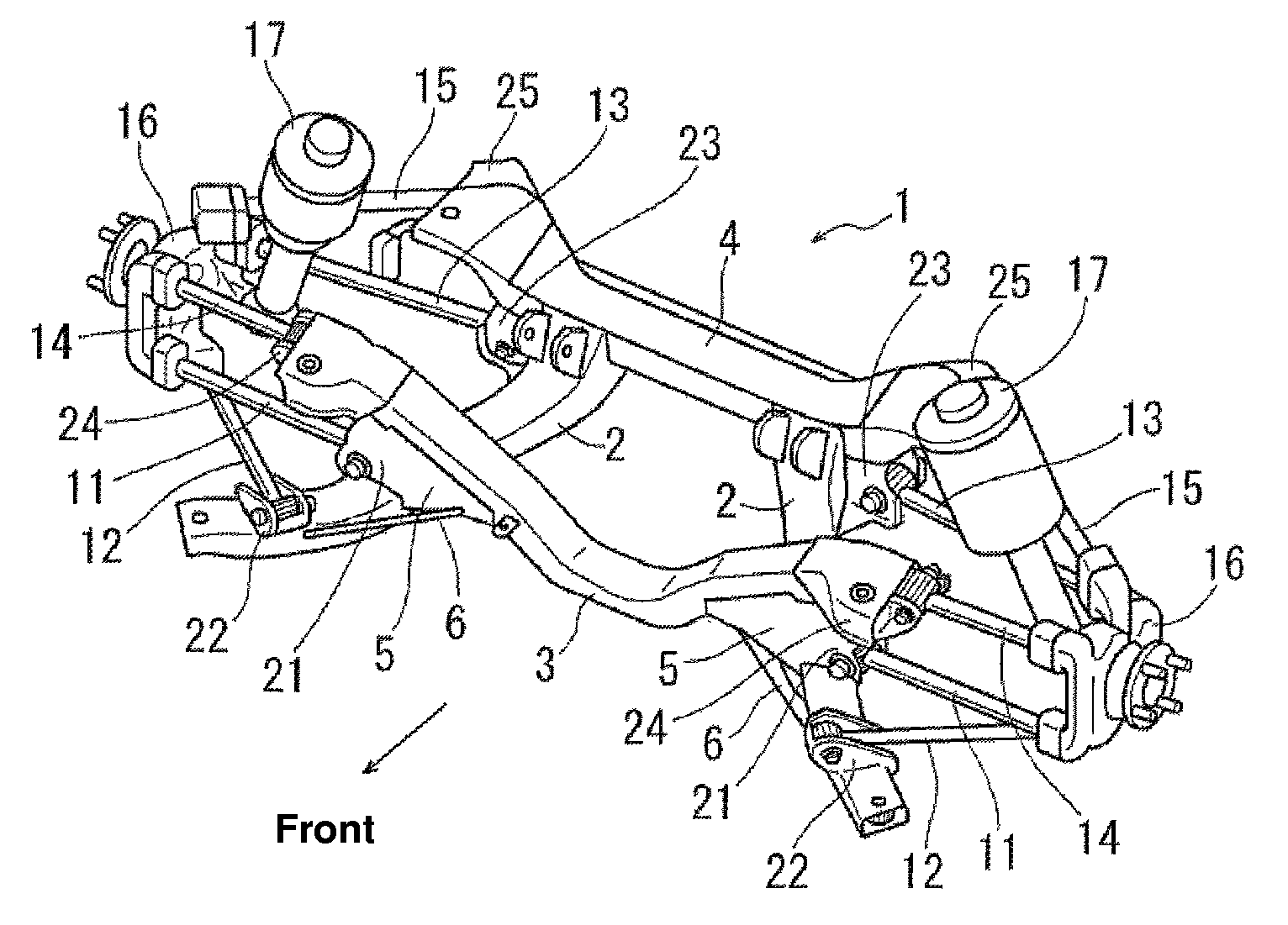
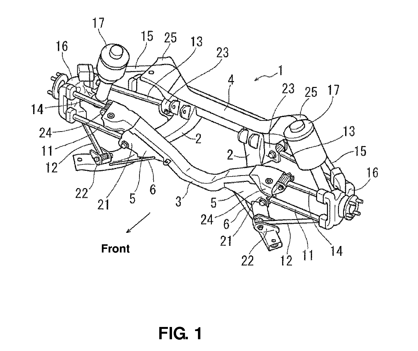
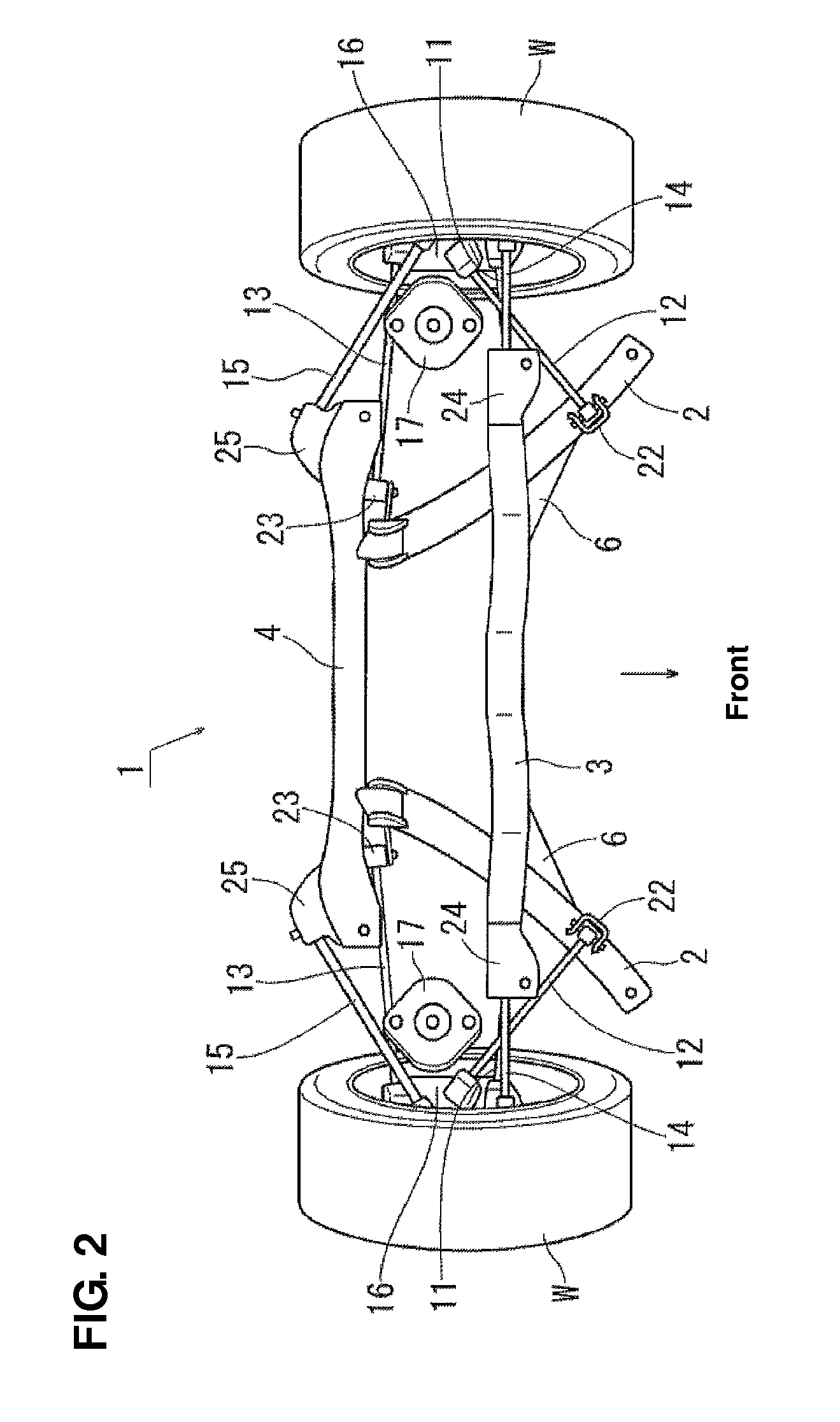
[0038]FIGS. 1-4 show a sub frame 1 of the present invention in a state in which suspension related components, such as suspension links, are assembled. FIGS. 5-7 show the sub frame 1 in a state in which the suspension related components are removed. In the figures, reference character W denotes a wheel and reference character R denotes a road surface.

[0039]In FIGS. 1-7, reference character 2 denotes a pair of right-and-left side members, reference character 3 denotes a front cross member, reference character 4 denotes a rear cross member, and reference character 5 denotes a pair of right-and-left connecting brackets. These side members 2, front cross member 3, rear cross member 3 are made from metal (Fe-based metal or light metal, such as aluminum alloy, for example) and formed such that these have a closed cross section, respectively.

[0040]The rig...


PUM


Abstract

A sub frame attached to a vehicle-body rear portion from below comprises a pair of right-and-left side members and a front cross member which interconnects substantially respective central portions, in a vehicle longitudinal direction, of the side members. As attachment portions for attaching lower links, there are provided a central attachment portion which is provided at an interconnection portion between the side member and the front cross member, a front attachment portion which is provided at the side member at a position located in front of the interconnection portion, and a rear attachment portion which is provided at the side member at a position located in back of the interconnection portion. Thereby, a sub frame structure of an automotive can be superior in the light weight, ensuring the support rigidity of the suspension links.

Description

BACKGROUND OF THE INVENTION[0001]The present invention relates to a sub frame structure of an automotive vehicle.[0002]In an automotive vehicle, a sub frame is attached to a vehicle-body rear portion and suspension links and other components are attached to the sub frame. In general, the sub frame to which the suspension links are previously assembled is attached to the vehicle-body rear portion from below.[0003]Increasing the rigidity of a vehicle body where the suspension links are attached can generally improve the driver's feelings of responsibility and rigidity when the automotive vehicle makes a turn. Japanese Patent Laid-Open Publication No. 2009-114652 proposes that a brace member is additionally provided to increase the rigidity of the vehicle body where the suspension links are attached.[0004]Improving the fuel economy has been recently desired additionally for the rigidity improvement. Accordingly, it is desirable that the sub frame is made properly light, ensuring the ne...

Claims


Application Information

Patent Timeline
Patent Type & Authority Patents(United States)
IPC IPC(8): B62D21/11
CPCB62D21/11B60G3/20B60G7/02B60G2200/18B60G2204/143B60G2204/15
Inventor OKUYAMA, KAZUHIROANDOU, FUMITAKAHIRAMATSU, MASAYA
Owner MAZDA MOTOR CORP
Learn More