Brake disc and brake disc manufacturing method

a technology of brake discs and manufacturing methods, which is applied in the direction of brake discs, foundry patterns, foundry moulding apparatus, etc., can solve the problems of drum brakes that do not provide sufficient brake force, and achieve the effects of reducing weight, increasing fuel efficiency, and high heat radiation efficiency and durability

Active Publication Date: 2020-06-30
KOREA AUTOMOTIVE TECH INST
View PDF18 Cites 0 Cited by
  • Summary
  • Abstract
  • Description
  • Claims
  • Application Information

AI Technical Summary

Benefits of technology

[0018]As described above, according to an embodiment of the present invention, since a cast iron brake disc is manufactured by inserting a porous metal block thereinto, a weight reduction effect may be ensured and the thickness of upper and lower plates may be reduced to about 3 mm. Since an open-cell-type porous metal block having a pore size of 20 pores per inch (ppi) (2 mm to 3.5 mm) has a surface area of 1,100 m2 / m3 and thus achieves high heat radiation efficiency and durability, an increase in fuel efficiency and a reduction in braking distance may be achieved. In addition, since the open-cell-type porous metal block has an extremely high surface area ratio per unit volume, an ultra light weight, a high strength, a high processability, a high impact resistance, a high noise absorbability, and sound absorption and electromagnetic shielding characteristics, the above-described effects may be achieved when the brake disc is manufactured using the open-cell-type porous metal block. A brake disc and a brake disc manufacturing method having the above effects may be implemented. However, the scope of the present invention is not limited thereto.

Problems solved by technology

Currently, since many technologies for achieving stability of a vehicle based on braking, e.g., anti-lock braking (ABS) and vehicle dynamic steering (VDS) / electronic stability program (ESP), have been developed, the drum brake which does not provide a sufficient braking force due to expansion when used repeatedly is not used and the disc brake is used for rear wheels as well as front wheels.

Method used


Image

  • Brake disc and brake disc manufacturing method
  • Brake disc and brake disc manufacturing method
  • Brake disc and brake disc manufacturing method

Examples


Embodiment Construction

Technical Problem

[0005]However, the method of manufacturing a brake disc by bond-casting cast iron and aluminum (Al) merely achieves a weight reduction rate of only about 40%. The method of manufacturing a brake disc by casting cast iron and then inserting metal foam thereinto has a very complex manufacturing process, does not easily achieve uniformity in closed-cell-type metal foam, and is not easily applicable due to a difference in continuous heating.

[0006]The present invention provides a brake disc and a brake disc manufacturing method capable of ensuring a weight reduction effect, achieving high heat radiation efficiency and durability, and thus achieving an increase in fuel efficiency and a reduction in braking distance. However, the scope of the present invention is not limited thereto.

Technical Solution

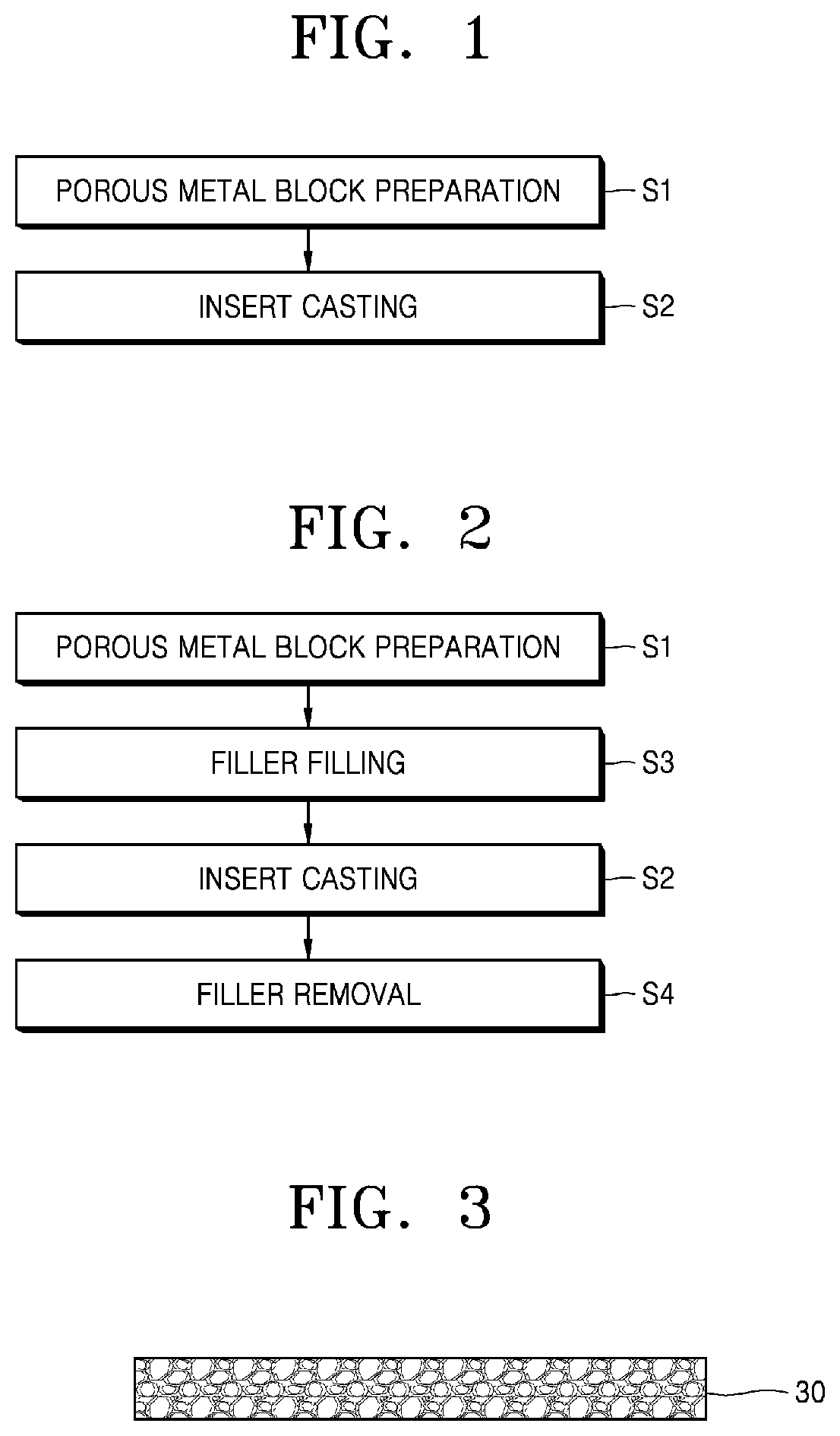
[0007]According to an aspect of the present invention, there is provided a brake disc manufacturing method including a porous metal block preparation operation for preparing a...


PUM

PropertyMeasurementUnit
thicknessaaaaaaaaaa
thicknessaaaaaaaaaa
pore sizeaaaaaaaaaa

Abstract

Provided are a brake disc and a brake disc manufacturing method. The brake disc manufacturing method may include a porous metal block preparation operation for preparing a porous metal block having a plurality of pores therein, and an insert casting operation for mounting the porous metal block in a mold and casting a disc plate material to manufacture a brake disc.

Description

TECHNICAL FIELD[0001]The present invention relates to a brake disc and a brake disc manufacturing method, and more particularly, to a brake disc and a brake disc manufacturing method used for a braking system of a vehicle.BACKGROUND ART[0002]In general, a vehicle brake is mainly divided into a disc brake and a drum brake. The disc brake generates a braking force based on friction created using calipers to squeeze pads against both sides of a disc that rotates together with a wheel. The drum brake obtains a braking force by squeezing brake shoes with linings (a friction material) into a drum that rotates together with a wheel.[0003]Currently, since many technologies for achieving stability of a vehicle based on braking, e.g., anti-lock braking (ABS) and vehicle dynamic steering (VDS) / electronic stability program (ESP), have been developed, the drum brake which does not provide a sufficient braking force due to expansion when used repeatedly is not used and the disc brake is used for ...

Claims


Application Information

Patent Timeline
Patent Type & Authority Patents(United States)
IPC IPC(8): F16D65/12B22D29/00B22D19/04B22D17/02B22D19/02B22D25/00B22D17/00F16D65/02C22C37/10
CPCB22D25/005B22D19/04B22D29/00B22D29/006B22D17/00B22D19/02F16D65/12F16D65/125B22D29/005F16D2200/0013C22C37/10F16D2250/0015F16D2065/132B22D19/00B22C9/046
Inventor SUNG, SI YOUNGHAN, BEOM SUCKKIM, SE HOONSHIN, JAE HYUKKIM, JIN PYEONG
Owner KOREA AUTOMOTIVE TECH INST
Why Eureka
Try Eureka