Head-rest of a vehicle seat

a headrest and vehicle seat technology, applied in the direction of chairs, pedestrian/occupant safety arrangements, vehicular safety arrangements, etc., can solve the problems of cervical spine whiplash injury, extreme extension movement, overextension of spinal neck muscles, etc., and achieve high functional reliability, cost-effective and compact manufacturing, and simplified structure of the headrest.

Inactive Publication Date: 2014-10-14
FACHHOCHSCHULE KAISERSLAUTERN +2
View PDF10 Cites 13 Cited by
  • Summary
  • Abstract
  • Description
  • Claims
  • Application Information

AI Technical Summary

Benefits of technology

[0010]As a first advantage of the invention, this results in a completely energy-autonomous operation of the headrest. Since the energy for setting up the lateral supporting surfaces comes from the kinetic energy of the head when being thrust into the headrest, it is not necessary to supply external energy.
[0011]Due to the kinematic coupling of the individual function units, it is also possible to dispense with a complex sensor system and a control device. This substantially simplifies the structure of a headrest according to the invention and permits it to be manufactured cost-effectively and compactly. The simplicity of the design also results in a high functional reliability, since the number of possible fault sources is inherently limited, due to the small number of parts.
[0012]Another advantage of the invention is derived from the direct setup of the lateral supporting surfaces as early as the time at which a head is thrust into the headrest. The completely instantaneous functionality resulting therefrom ensures that the protective action of the lateral supporting areas may take place very early on and therefore extremely effectively.
[0013]A first part of the embodiments of the invention according to the invention is based on the utilization of the fin ray effect. In this case, due entirely to a special lattice-like design, a supporting structure is created whose free ends move counter to the deformation direction during a deformation of the central area and form lateral supporting surfaces. This way of implementing the invention may consequently be carried out without great complexity and also has the advantage that the lateral supporting surfaces automatically adapt to the contour of the head and thus to its particular position. This results in an equalized and thus reduced pressure distribution on the head of a vehicle occupant.
[0014]In an embodiment of the invention, the lattice-like supporting structure comprises a front supporting strap and a rear supporting strap, which are opposite each other and are connected to each other at their facing ends at an acute angle β, while the two remaining ends end at a mutual distance from each other. The two supporting straps are connected to each other by articulated cross-struts. The cross-struts are advantageously positioned at an angle in relation to the front strap, i.e., they are inclined at an angle α in relation to the front supporting strap.
[0015]The selection of angle β has an influence on the extent of the counter-movement of the supporting surfaces produced by a deformation and the stresses generated in the supporting structure by the deformation. At small angles β, a great counter-movement and high material stresses occur. Conversely, a large angle β generates smaller induced counter-movements and a smaller material load. By suitably selecting angle β, therefore, the movement of the supporting surfaces as well as the material loads produced thereby may be determined. Taking these circumstances into account, angle β in the range of 10° to 25°, preferably from 15° to 20°, has proven to be advantageous.

Problems solved by technology

This is caused by the fact that, during an accident, the abrupt acceleration of the vehicle occupants in the direction of travel results in an extreme extension movement of the head, which is overlaid by a simultaneous rotary and wobbling movement, usually around multiple spatial axes.
As a result, the spinal neck musculature is overextended, which ultimately results in the aforementioned cervical spine whiplash injury.
The additional structural complexity caused by the external drive, including the associated components, which makes the headrest more expensive, has proven to be disadvantageous.
Since the additional components must be accommodated in the headrest or the vehicle seat, the worthwhile implementation of a headrest of a vehicle seat having a compact structure is problematic.

Method used


Image

  • Head-rest of a vehicle seat
  • Head-rest of a vehicle seat
  • Head-rest of a vehicle seat

Examples


Embodiment Construction

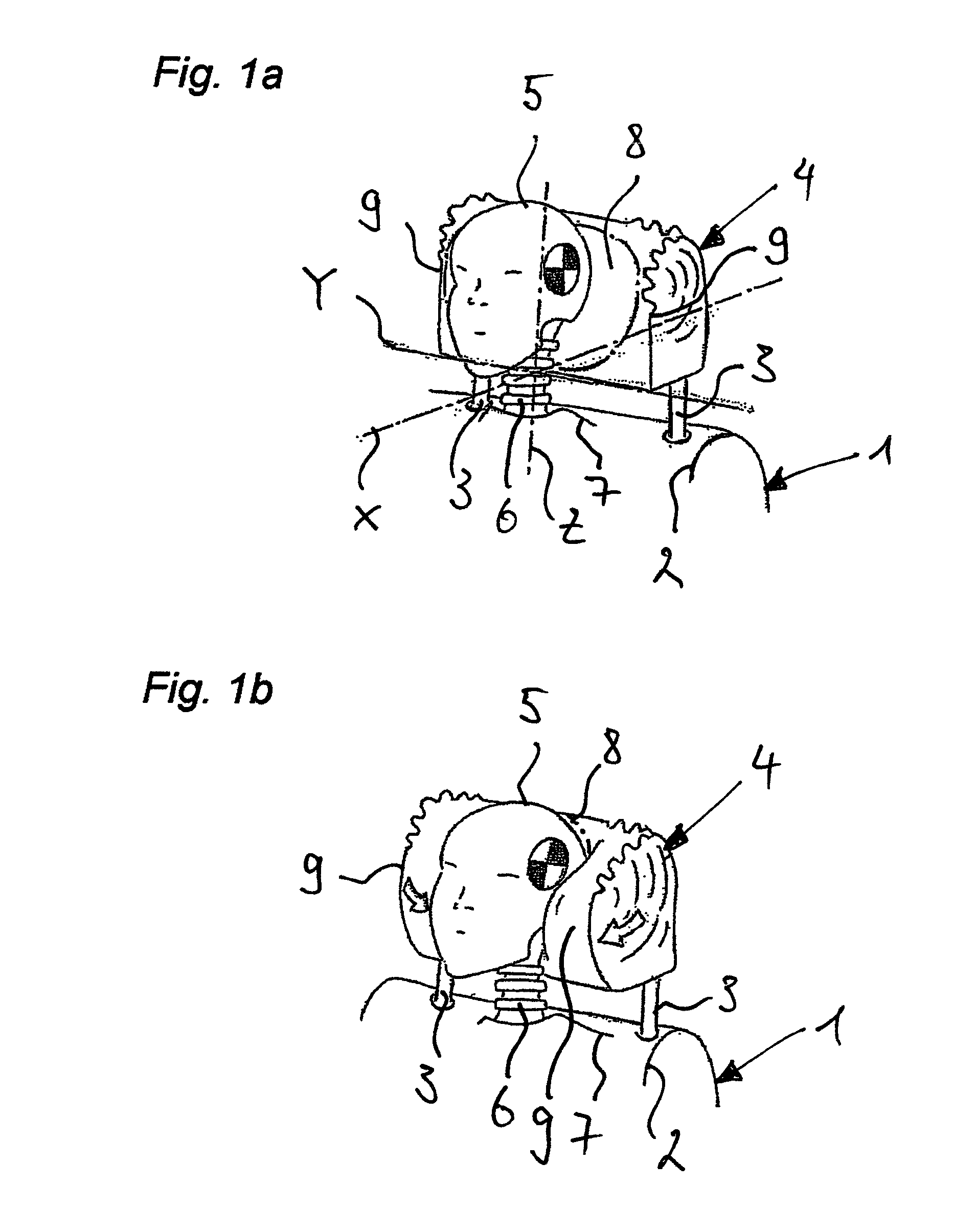
[0037]FIG. 1a shows the upper area of a vehicle seat 1 from whose backrest 2 two holding rods 3 project for fastening a headrest 4 according to the invention. Head 5, including cervical spine 6, of a vehicle occupant whose torso is indicated by reference numeral 7 is shown in front of headrest 4.

[0038]In addition, FIG. 1a shows three orthogonally disposed spatial axes, of which the horizontal spatial axis pointing in the direction of travel is identified by X, the vertical spatial axis is identified by Z, and the spatial axis pointed transversely to the direction of travel is identified by Y. Axes X and Z span the median plane in relation to the vehicle passengers.

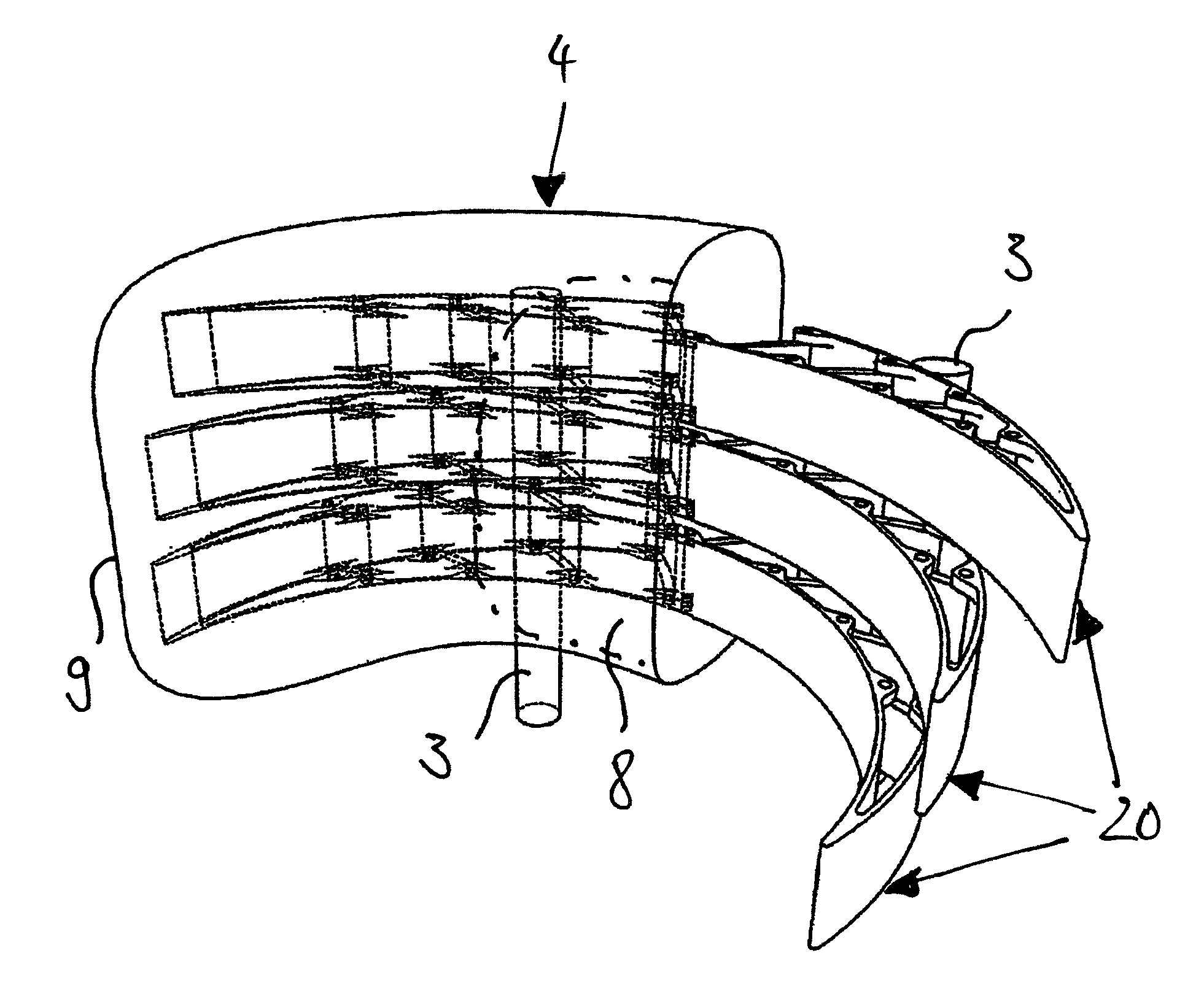
[0039]FIG. 1a shows the situation before an accident event occurs, in which head 5 is held at a distance from headrest 4. The area of headrest 4 which is located behind head 5 in the direction of travel has a central impact zone 8; the adjacent area on both sides in the Y direction is formed by lateral supporting surfaces ...


PUM


Abstract

A head-rest of a vehicle seat with a deformable central supporting body which forms an impact zone for the head of a vehicle occupant and into which the kinetic energy of the head in the event of an accident is admitted. On both sides of the impact zone the central supporting bodies are joined by lateral supporting surfaces which are extendable out of the plane of the head-rest in the direction of travel in order to laterally support the head. In order to avoid or at least to reduce the risk of a cervical-spine whiplash injury, it is proposed according to the invention that the head-rest comprises a device for absorbing the energy admitted into the central supporting body and for outputting the absorbed energy in order to activate lateral supporting surfaces.

Description

[0001]This nonprovisional application is a continuation of International Application No. PCT / EP2011 / 006345, which was filed on Dec. 15, 2011, and which claims priority to German Patent Application No. DE 10 2010 054 651.8, which was filed in Germany on Dec. 15, 2010, and which are both herein incorporated by reference.BACKGROUND OF THE INVENTION[0002]1. Field of the Invention[0003]The present invention relates to a head rest for a vehicle seat.[0004]2. Description of the Background Art[0005]A frequent type of injury in motor vehicle accidents, in particular in rear-end collisions, is the cervical spine whiplash injury. This is caused by the fact that, during an accident, the abrupt acceleration of the vehicle occupants in the direction of travel results in an extreme extension movement of the head, which is overlaid by a simultaneous rotary and wobbling movement, usually around multiple spatial axes. As a result, the spinal neck musculature is overextended, which ultimately results ...

Claims


Application Information

Patent Timeline
Patent Type & Authority Patents(United States)
IPC IPC(8): B60N2/42B60R22/28B60N2/427B60N2/48
CPCB60N2/42709B60N2/4885B60N2/4882B60N2/888B60N2/885
Inventor GAENG, LUTZ-ACHIMMUENCH, PETERFELDER, HANNOKRICK, CHRISTOPHSCHLUETER, SEBASTIANSCHAAL, BENJAMINKALKA, FRANKOTTE, MICHAELGOUTIER, RALFZIMMER, MARKUSWAIZ, VERASCHATKE, PAULEHMER, SUSANNEMEYER, STEFANKLEIN, FRANK
Owner FACHHOCHSCHULE KAISERSLAUTERN
Why Eureka
Try Eureka