
Cleanout boom

a technology of cleaning boom and boom, which is applied in the field of plumbing, can solve the problems of a device, a potentially dangerous situation, and a risk for both the plumber on the roof and the other people on the ground below

Inactive Publication Date: 2015-10-01
LOPEZ LUIS F +1
View PDF1 Cites 3 Cited by
  • Summary
  • Abstract
  • Description
  • Claims
  • Application Information

AI Technical Summary

Benefits of technology

This invention is about a device that can be used to clean out or inspect pipes from the ground, which increases safety for workers and reduces insurance costs. The device is also easier and faster to use than traditional methods, and it is affordable to manufacture and maintain.

Problems solved by technology

None of them, however, includes a device that can be operated from the ground to attach onto a roof vent stack and effectively clean out and inspect the pipe without a person ever getting onto the roof of the structure.
This creates a potentially dangerous situation involving personnel climbing a latter.
Either situation carries with it risk for both the plumber on the roof and other people on the ground below.
Further, damage can result from a plumber on the roof damaging the roof itself or injuring himself by stepping through soft or damaged roofing structure when carrying heavy equipment.
The boom has a limited range of reach.
The truck can damage sensitive landscaping or other elements.
The boom trucks are expensive and also require a skilled operator to work safely.
Each is expensive and potentially dangerous.

Method used


Image

  • Cleanout boom
  • Cleanout boom
  • Cleanout boom

Examples


Embodiment Construction

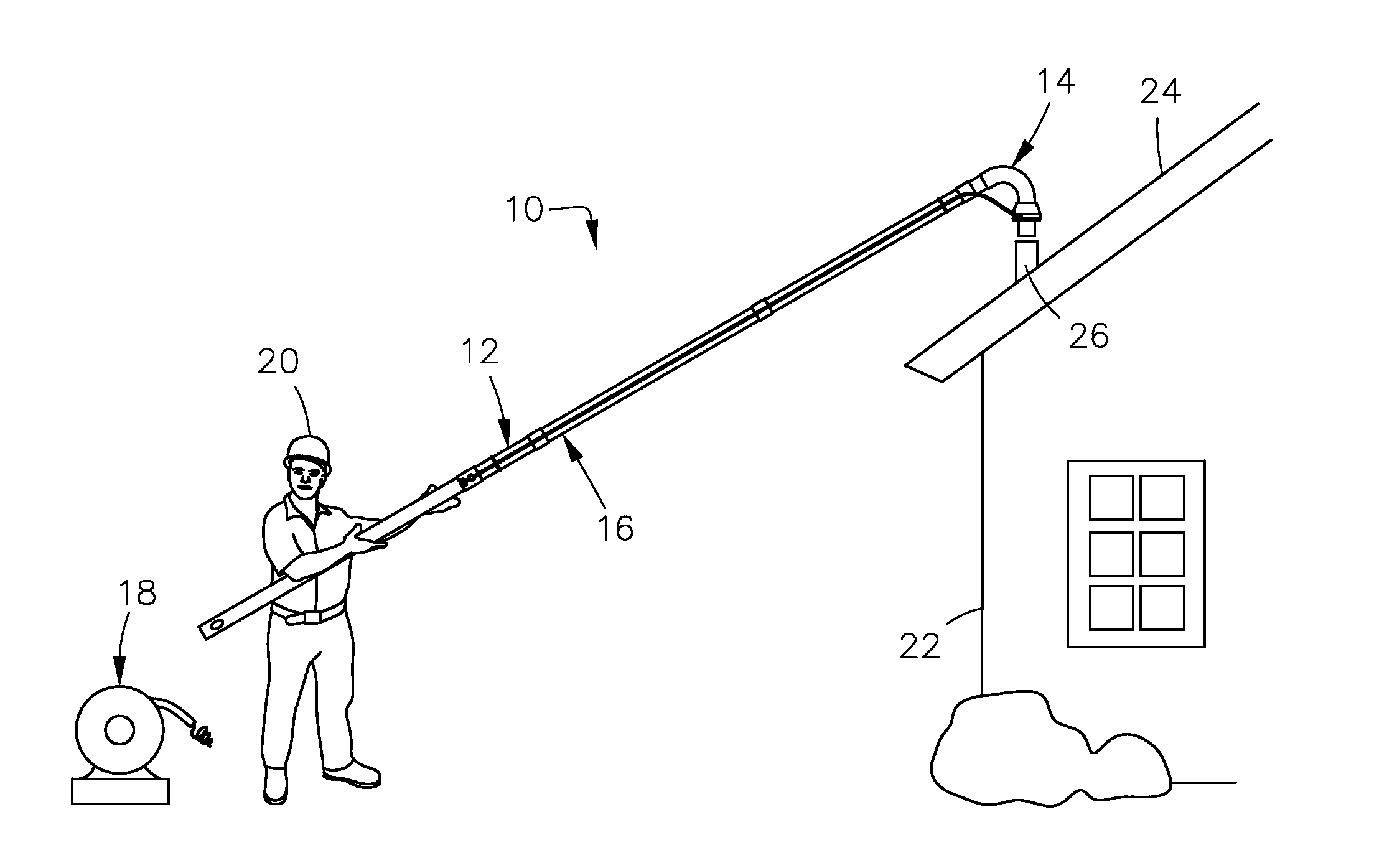
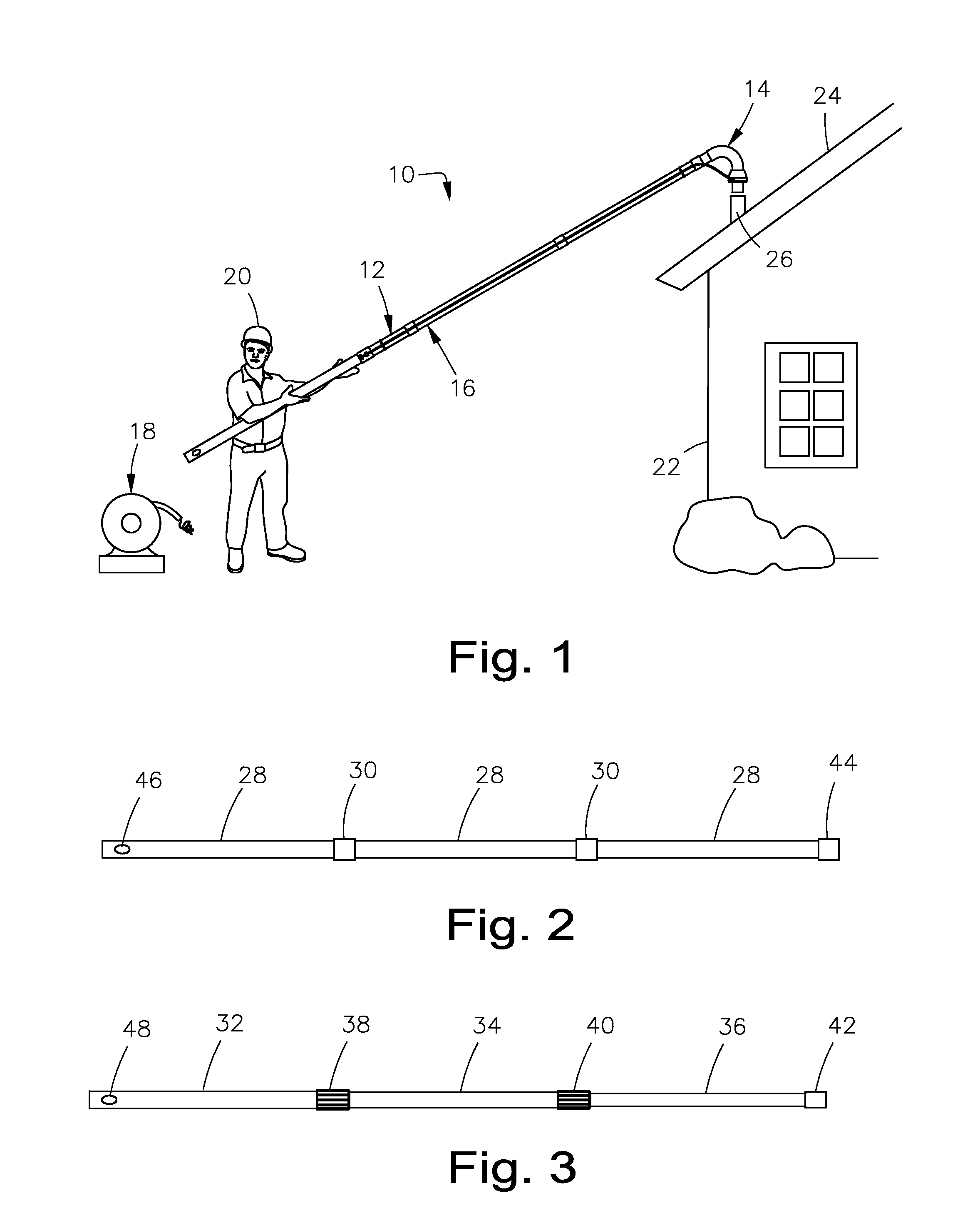
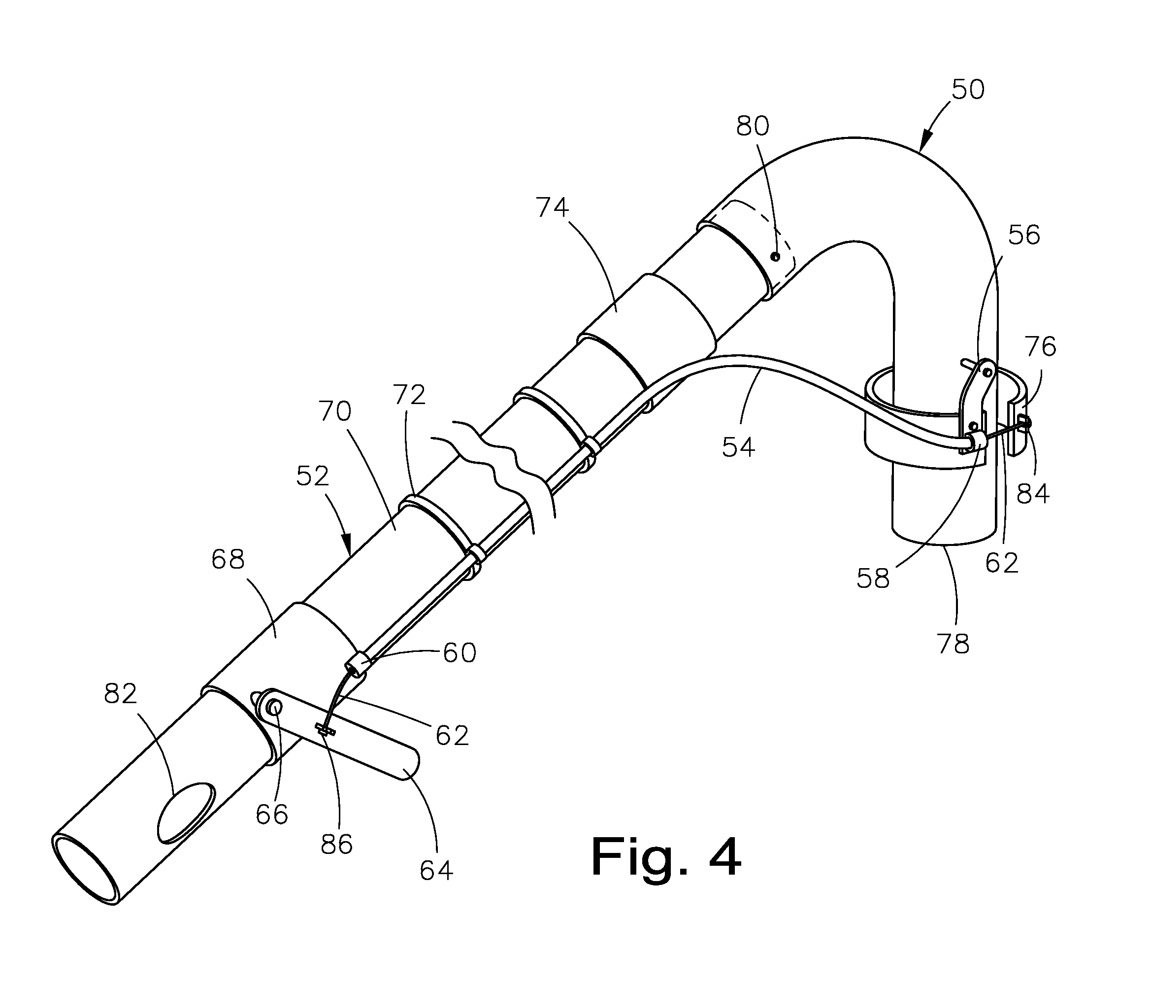
[0034]Referring now to the drawings, where the present invention is generally referred to with numeral 10, it can be observed in FIG. 1 that it basically includes a pole assembly 12, a head assembly 14, a clamp assembly 16 and a reamer assembly 18. An operator 20, a house 22 and a vent 26 are shown for context and are not considered elements of the device.

[0035]It can be seen in FIG. 1 that the device is generally used by an operator 20 on the ground near a house 22 or other structure. The pole assembly 12 is controlled by the operator 20 on the lower end. On the upper end of the pole assembly 12 is affixed a head assembly 14.

[0036]The head assembly 14 is positioned over a vent 26 pipe on the roof 24 of the house 22 by the operator 20 manipulating the pole assembly 12. Once the head assembly 14 is set onto the vent 26, the operator can activate the clamp assembly 16 from the ground to gain a positive connection between the head assembly 14 and the vent 26. The operator 20 ideally ne...


PUM


Abstract

A cleanout boom for guiding a plumbing snake, pressure washer, camera or a similar apparatus into a vent pipe on the roof of a structure. A head assembly with a remote mechanism to attach the head assembly to the vent. The device can be entirely operated from the ground.

Description

BACKGROUND OF THE INVENTION[0001]1. Field of the Invention[0002]The present invention relates to plumbing, and more particularly, to cleaning and inspecting roof vents and other plumbing pipes.[0003]2. Description of the Related Art[0004]Modern plumbing systems in residential and commercial structures are generally entirely gravity driven on the drain side of the equation. For water to quickly drain out of the bottom of the system, for example into a sewer or septic system, a vent must allow air into the pipes above the drain.[0005]Vents are commonly vertical pipes that traverse a structure from the pipes in the walls or under the floors up through the roof.[0006]Vent pipes, sometimes referred to as vent stacks, conveniently provide a point of access into the plumbing system for inspection, repair and, most commonly, clean out.[0007]It is common practice for plumbers to insert long wire snakes into roof vents that travel down the vent then into the drain pipes inside or under the st...

Claims


Application Information

Patent Timeline
Patent Type & Authority Applications(United States)
IPC IPC(8): F16L37/00E04D15/00E04D13/076F16L27/00F16L19/06
CPCF16L37/002F16L27/00E04D15/00E04D13/0765E04D15/006F16L19/06F24F7/02F24F2221/22
Inventor LOPEZ, LUIS F.PACIN, EMMANUEL
Owner LOPEZ LUIS F
Learn More