Nasal dilator and method of manufacture

a dilator and nasal tube technology, applied in the field of nasal tube dilator and manufacturing method, can solve the problems of affecting breathing, sleep disturbance, irregularities and general discomfort, and typically having limited properties, so as to reduce waste, reduce cost, and ensure the effect of dilating

Active Publication Date: 2014-10-14
HORIZON IP TECH LLC
View PDF49 Cites 44 Cited by
  • Summary
  • Abstract
  • Description
  • Claims
  • Application Information

AI Technical Summary

Benefits of technology

[0023]The external nasal dilator of the present invention comprises a laminate of vertically stacked material layers. The laminate is held together by an adhesive substance disposed on at least one flat surface side of at least one of its constituent layers. The laminate forms a unitary, or single body, truss. Each layer includes one or more members, and a member may further include one or more components. The truss features horizontal regions, including first and second end regions adapted to engage outer wall tissues of first and second nasal passages, respectively, and an intermediate region adapted to traverse a portion of a nose located between the first and second nasal passages and joining the end regions. In use the dilator acts to stabilize and / or expand the nasal outer wall tissues and prevent said tissues from drawing inward during breathing. The truss is configured to be comfortable on the tissue engaged and to be easily removed from the tissue with little or no stress thereto.
[0025]Embodiments of the present invention include, without limitation, new and non-obvious means to efficiently manufacture with minimal waste nasal dilator devices and the constituent layers, members and components thereof. Preferred embodiments also include methods for simultaneously fabricating identical, non-identical, symmetric or asymmetric dilator members, components thereof, and finished nasal dilator devices with equal efficiency and with at the same or lower cost as traditional methods. Embodiments further include: means to assist centering on the nose of a wearer comprising a separation, projection or other index marker located at the intermediate region of the dilator; a resilient member or component thereof having a gradiently reduced width; dilator layers, members or components made from materials which are transparent or translucent; and means for incorporating promotional printing and / or contrasting colors (such as team sports colors) into the dilator fabrication process.
[0026]It is the principal objective of this invention to provide nasal dilator devices which overcome the aforementioned limitations and disadvantages of prior dilator devices. A more specific objective of the present invention is to provide nasal dilators and methods of manufacture that minimize material waste and reduce traditional manufacturing cost by configuring device layers and / or members to be fabricated, in whole or part, along common lines or edges that simultaneously define at least a portion of their peripheral dimensions while establishing a spaced apart relationship therebetween without sacrificing usable material to do so. A further objective of this invention is to provide nasal dilator devices that are configured to allow their constituent layers to be fabricated so as to return a greater number of individual dilator units, layers, members or components thereof per a given quantity of material, and / or to maximize the percentage of a given quantity of raw material used in the fabrication process.
[0027]A still further objective of this invention is to provide nasal dilator devices that are less expensive to manufacture, that utilize manufacturing techniques that create efficiencies and utilize less material without increasing fabrication and assembly costs, that use less expensive materials, that use less overall material in device construction, that are simple and easy to use, that effectively dilate external tissue, that provide a gradiently reduced spring biasing force extending from the intermediate region to at least a portion of at least one end region of the dilator, that provide disparate spring biasing force to opposing nasal passages, and that are more affordable to the user than prior art dilator devices.

Problems solved by technology

A portion of the human population has some malformation of the nasal passages which interferes with breathing, including deviated septa and swelling due to allergic reactions.
Blockage of the nasal passages as a result of malformation, symptoms of the common cold or seasonal allergies are particularly uncomfortable at night, and can lead to sleep disturbances, irregularities and general discomfort.
Said material, such as a spunlaced polyester nonwoven fabric, typically has properties which permit limited, primarily plastic and somewhat elastic deformation within the thickness thereof.
These limitations include limited skin surface area adjacent the nasal passages, adhesive engagement vs. delaminating spring biasing forces, device comfort and durational longevity, and economical fabrication and assembly of dilator components.
Firstly, tissues associated with and adjacent the nasal passages have limited skin surface areas to which dilation may be applied.
Secondly, nasal dilators are, of necessity, releasably engaged to outer wall tissues by use of pressure sensitive adhesives.
While these devices provide sufficient dilation of nasal passageway tissue and thus provide the claimed benefit to the vast majority of users, they are not configured to fully overcome the aforementioned limitations.
Of course a separate packaging operation has a corresponding additional cost.
Dilator manufacturers typically weigh the cost of wasted material against the cost of a separate packaging operation.
Material between the web-connected resilient members and finished dilators is wasted.
In the modern consumer product market, nasal dilator innovation and competitive value propositions to resellers and consumers have been limited.

Method used


Image

  • Nasal dilator and method of manufacture
  • Nasal dilator and method of manufacture
  • Nasal dilator and method of manufacture

Examples


Embodiment Construction

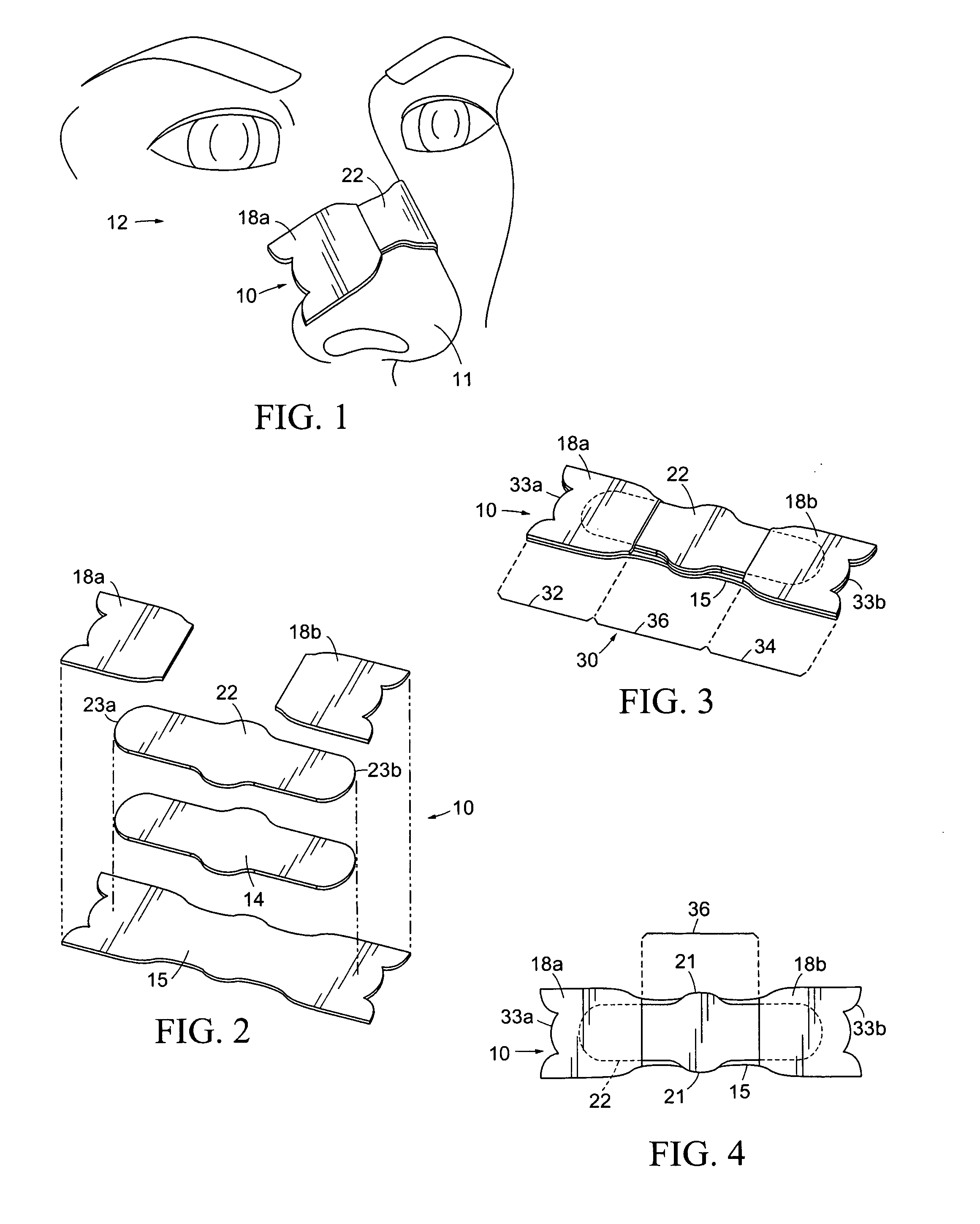
[0054]An embodiment of a nasal dilator, 10, in accordance with the present invention, is illustrated in FIG. 1 which shows dilator 10 engaged to a nose, 11, seen as a portion of a human face, 12.

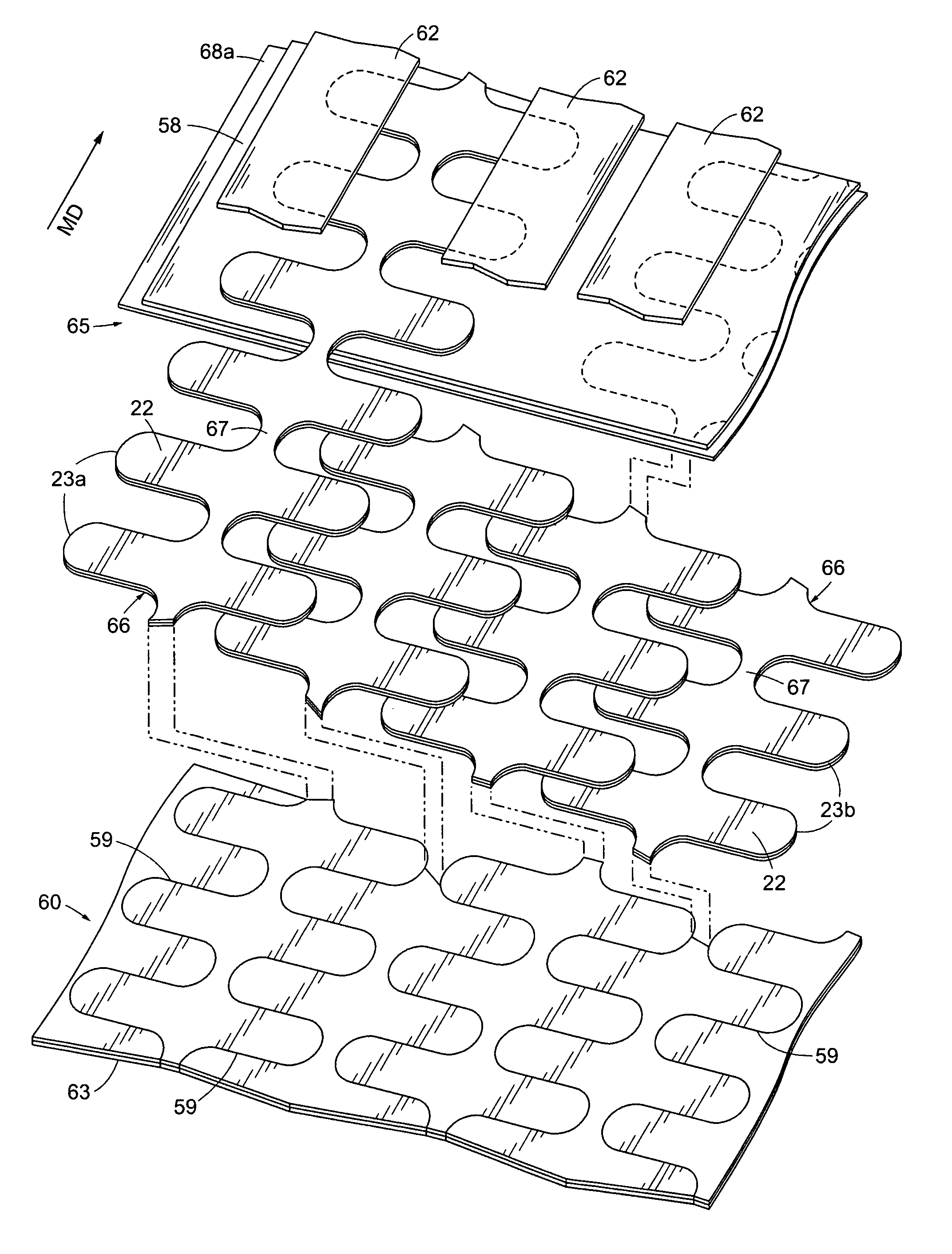
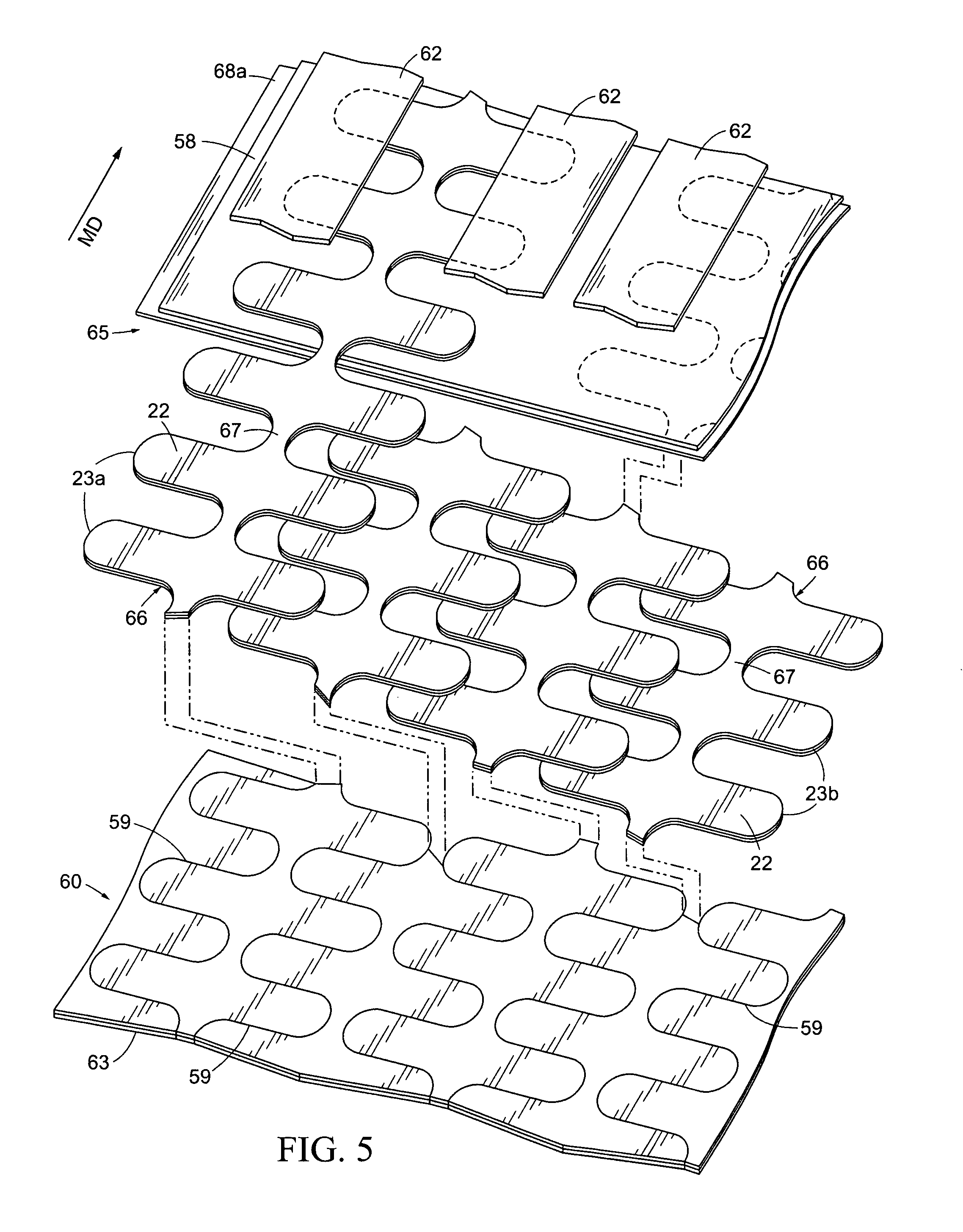
[0055]As seen in FIG. 2, dilator 10 comprises a laminate of vertically stacked material layers. Said layers comprise a base layer having at least one base member, 14, a resilient layer comprised of at least one resilient member, 22, and a cover layer composed of cover members, 18a and 18b. The layers may be laminated to each other by any suitable means including heat or pressure bonding, but are preferably laminated by an adhesive substance disposed on at least one flat surface side of each thereof. Cover members 18a and 18b are dimensionally configured to correspond to at least portions of the skin surfaces of outer wall tissues adjacent first and second nasal passages, respectively. The cover and / or base layers serve as the primary engagement element while the resilient layer provides the ...


PUM

PropertyMeasurementUnit
thicknessaaaaaaaaaa
thicknessaaaaaaaaaa
lengthaaaaaaaaaa

Abstract

A nasal dilator manufacturing process reduces waste by cutting nested strips of flexible resilient members interconnected by waste webs from a sheet of resilient-layer material. The nested strips are incorporated into a fabrication matrix with other layers (e.g. base or cover layers), then individual nasal dilators are formed by cutting through the matrix around a peripheral outline of a dilator, said cutting severing the nested strips that are part of the fabrication matrix near the waste webs between the flexible resilient members.

Description

RELATED APPLICATIONS[0001]This application claims the benefit of U.S. Provisional Application No. 60 / 888,543 filed Feb. 6, 2007 and 61 / 035,972 filed Mar. 12, 2008.FIELD OF THE INVENTION[0002]The present invention relates to apparatus and methods of dilating external tissue. As disclosed and taught in the preferred embodiments, the tissue dilator devices and methods of fabrication of tissue dilators are particularly suitable for use as external nasal dilators for supporting, stabilizing, and dilating nasal tissues adjacent and overlying nasal airway passages, including the nasal valve and / or the vestibule areas thereof.BACKGROUND OF THE INVENTION[0003]A portion of the human population has some malformation of the nasal passages which interferes with breathing, including deviated septa and swelling due to allergic reactions. A portion of the interior nasal passage wall may draw in during inhalation to substantially block the flow of air. Blockage of the nasal passages as a result of m...

Claims


Application Information

Patent Timeline
Patent Type & Authority Patents(United States)
IPC IPC(8): A61M29/00A61F5/08
CPCA61F5/08Y10T156/1056Y10T156/1052Y10T156/1062Y10T156/1075Y10T156/1082Y10T156/1057
Inventor IERULLI, JOSEPH, VINCENT
Owner HORIZON IP TECH LLC
Why Eureka
Try Eureka